Contents APCI-3003
Figures
Fig. 3-1: Correct handling ................................................................10
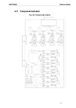
Fig. 4-1: Component scheme .........................................................15
Fig. 5-1: Types of slots.......................................................................16
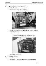
Fig. 5-2: Inserting the board .............................................................17
Fig. 5-3: Fastening the board at the back cover .............................17
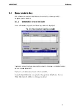
Fig. 6-1: New inserted board (example)...........................................19
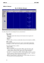
Fig. 6-2: ADDevice Manager............................................................20
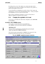
Fig. 6-3: ADDIREG registration program (example)...........................21
Fig. 7-1: 15-pin SUB-D male connector (analog inputs) ...................25
Fig. 7-2: Analog input at the PX 901-AG...........................................25
Fig. 7-3: 16-pin connector on a 15-pin SUB-D female connector....26
Fig. 7-4: Digital inputs and outputs at the PX 901-ZG .......................26
Fig. 7-5: Connection principle of the analog inputs.........................28
Fig. 7-6: Connection of the digital inputs .........................................28
Fig. 7-7: Connection of the digital outputs.......................................29
Fig. 7-8: Connection of the APCI-3003 to the screw terminal panels30
Fig. 8-1: Block diagram of the APCI-3003 ........................................31
Tables
Table 9-1: Supported software functions..........................................39
Table 9-2: Supported software samples for the APCI-3003 ..............42
6

