background image

Mounting and connection 

MSX-ilog-xx-xx 


www.addi-data.com 

15 

ADDI-DATA

®

PARTNER FÜR PRÄZISION


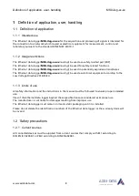
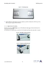
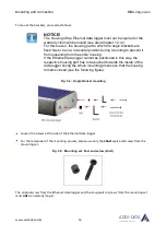
Fig. 3-6:  Mounting set: Original screw, seal and screw (long) 


Place a seal in one of the screw holes. 


Place the bracket on the seal. 


Fix the bracket with a short screw from the mounting set. 


Repeat these steps with the other screw holes. 

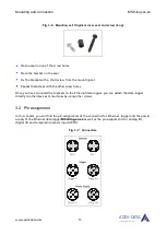
Once you have mounted the brackets on the Ethernet data logger, you can attach the data logger 
directly to other devices or machines by using other screws. 
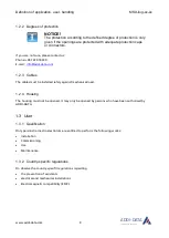
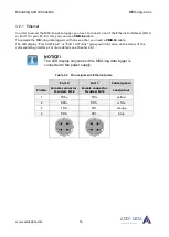
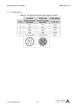
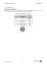
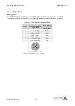
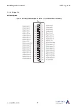
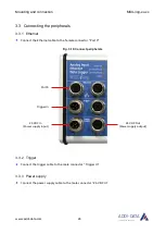
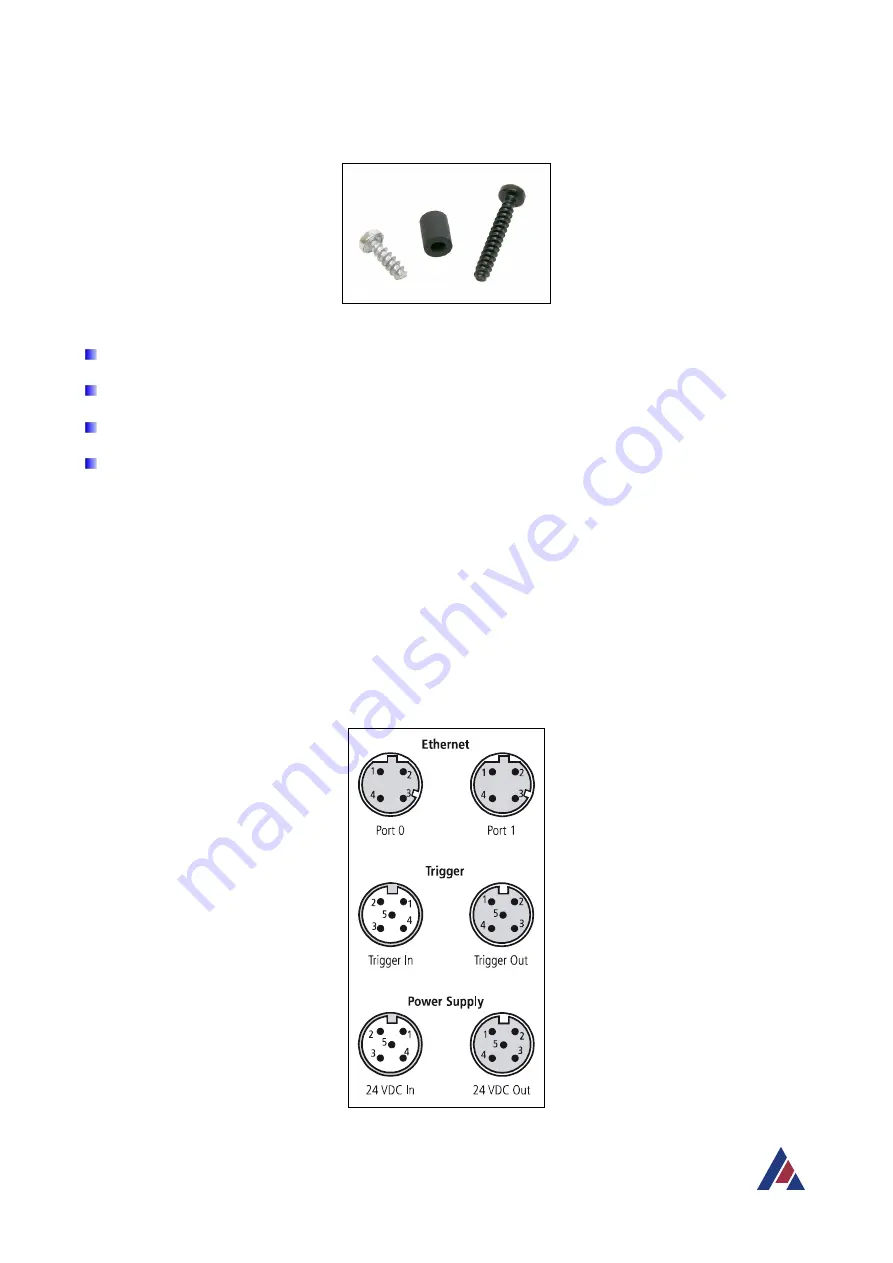
 

3.2  Pin assignment  

In this chapter, you will find the pin assignments of the connectors for Ethernet, trigger and the power 
supply of the Ethernet data logger 

MSX-ilog-xx-xx

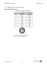
 as well as the pin assignments for analog I/O, 

digital I/O and temperature sensor inputs (RTD). 

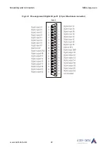
Fig. 3-7:  Connectors 


Summary of Contents for MSX-ilog Series

Page 1: ...ADDI DATA PARTNER FÜR PRÄZISION DIN EN ISO 9001 2015 certified Edition 02 12 11 2020 Technical Description MSX ilog xx xx Intelligent Ethernet data logger ...

Page 2: ...t information or disclosure of this information for use by third parties is not permitted unless this right has been granted by the product licence issued Non compliance with this could lead to civil and criminal proceedings ADDI DATA software product licence Please read this licence carefully before using the standard software The customer is only granted the right to use this software if he she ...

Page 3: ...ntation please contact us and ask for it Observe the instructions of this manual Make sure that you do not forget or skip any step We are not liable for damages resulting from the wrong use of the Ethernet data logger Pay attention to the following symbols NOTICE Designates hints and other useful information NOTICE Designates a possibly dangerous situation If the instructions are ignored the Ether...

Page 4: ...12 3 1 2 Angle bracket mounting 13 3 2 Pin assignment 15 3 2 1 Ethernet 16 3 2 2 Trigger 17 3 2 3 Power supply 18 3 2 4 Analog inputs 19 3 2 5 Analog outputs 20 3 2 6 Digital I O 21 3 2 7 Temperature sensor inputs RTD inputs 23 3 3 Connecting the peripherals 24 3 3 1 Ethernet 24 3 3 2 Trigger 24 3 3 3 Power supply 24 3 3 4 Sensors or actuators 25 3 4 LED display 26 3 4 1 Overview 26 3 4 2 Status L...

Page 5: ...tor 21 Fig 3 9 Pin assignment Digital I O port 1 37 pin D Sub male connector 22 Fig 3 10 Connect peripherals 24 Fig 3 11 Connect sensors or actuators example 25 Fig 4 1 Web interface Login window 32 Fig 4 2 Web interface Homepage 32 Fig 4 3 Acquisition Channel configuration master system 33 Fig 4 4 Acquisition Channel configuration slave system 34 Fig 4 5 Acquisition Slave systems 34 Fig 4 6 Acqui...

Page 6: ...ber 51 Fig 5 2 Disposal Label 52 Tables Table 3 1 Pin assignment Ethernet ports 16 Table 3 2 Pin assignment Trigger 17 Table 3 3 Trigger cables 17 Table 3 4 Pin assignment Power supply input and output 18 Table 3 5 Pin assignment Analog inputs 19 Table 3 6 Pin assignment Analog outputs 20 Table 3 7 Pin assignment RTD inputs 23 Table 3 8 LED display 26 Table 3 9 Status LED 27 ...

Page 7: ...he application the user and on handling the MSX ilog data logger 2 Brief description of the MSX ilog data logger functions and features 3 Information on mounting the MSX ilog data logger including pin assignments 4 Description of the MSX ilog web interface 5 Procedure for returning repairing etc or disposing of the MSX ilog data logger 6 Appendix with glossary and index 7 Contact and support addre...

Page 8: ...log xx xx must not be used in potentially explosive atmospheres The Ethernet data logger MSX ilog xx xx must not be used as electrical equipment according to the Low Voltage Directive 2014 35 EU 1 1 3 Limits of use All safety information and the instructions in the manual must be followed to ensure proper intended use Uses of the Ethernet data logger beyond these specifications are considered as i...

Page 9: ...ail info addi data com 1 2 3 Cables The cables must be installed safely against mechanical load 1 2 4 Housing The housing must not be opened It may only be opened by persons who have been authorised by ADDI DATA 1 3 User 1 3 1 Qualification Only persons trained in electronics are entitled to perform the following works Installation Commissioning Use Maintenance 1 3 2 Country specific regulations D...

Page 10: ...ons and updates If you have any questions do not hesitate to call us or to send us an e mail Phone 49 7229 1847 0 E mail info addi data com Manual download from the Internet The latest version of the technical manual for the Ethernet data logger MSX ilog xx xx can be downloaded for free at www addi data com NOTICE Before using the Ethernet data logger and in case of malfunction during operation ch...

Page 11: ...the number of acquisitions to be saved before the start trigger occurs Two start and three stop trigger types are available digital analog and time For each channel a high and low alarm level can be defined The recorded data can be exported in a CSV XML or JSON file A PC based application with a constant connection via Ethernet is also an option as is individual use as a stand alone terminal and s...

Page 12: ... 1 1 DIN rail mounting With the mounting set MX Rail1 you can attach the Ethernet data logger to a DIN rail Risk of injury If you have already mounted this Ethernet data logger on a DIN rail and want to transport it in a switch cabinet or in other systems please ensure that it is adequately secured for transport The Ethernet data logger could for example fall off the DIN rail which could cause dam...

Page 13: ...kwards until the top of the fastening clips engages with the DIN rail 3 1 2 Angle bracket mounting With the mounting set MX Screw you can fit the Ethernet data logger for direct attachment to machines or other devices According to your requirements you can fix all four brackets pointing either outwards or inwards Fig 3 2 Brackets pointing outwards Fig 3 3 Brackets pointing inwards ...

Page 14: ...e entire housing If the Ethernet data logger cannot be positioned in this way the respective housing part has to be pushed towards the inside of the data logger during the whole mounting process so that the housing remains closed see the following figure Fig 3 4 Angle bracket mounting Loosen the screws at the side of the Ethernet data logger For the remainder of the mounting process please use onl...

Page 15: ...eat these steps with the other screw holes Once you have mounted the brackets on the Ethernet data logger you can attach the data logger directly to other devices or machines by using other screws 3 2 Pin assignment In this chapter you will find the pin assignments of the connectors for Ethernet trigger and the power supply of the Ethernet data logger MSX ilog xx xx as well as the pin assignments ...

Page 16: ...ers with one another you need a CMX 7x cable The LED display Port 0 ACT Link or Port 1 ACT Link gives you information on the status of the corresponding interface For more details see Chapter 3 4 1 NOTICE The LED display only works if the MSX ilog data logger is connected to the power supply Table 3 1 Pin assignment Ethernet ports Port 0 Port 1 Cable green Pin No Female connector D coded M12 Femal...

Page 17: ...ted not connected Please use a shielded trigger cable Table 3 3 Trigger cables Name Cable end Length CMX 40 Open end female connector 5 pin 1 5 m CMX 41 Open end female connector 5 pin 3 m CMX 42 Open end female connector 5 pin 5 m CMX 43 Open end female connector 5 pin 10 m CMX 49 Open end female connector 5 pin on request CMX 50 Male connector 5 pin female connector 5 pin 1 5 m CMX 51 Male conne...

Page 18: ...ZISION 3 2 3 Power supply Table 3 4 Pin assignment Power supply input and output 24 VDC In 24 VDC Out Cable black Pin No Male connector 5 pin M12 Female connector 5 pin M12 Lead colour 1 24 V 24 V brown 2 24 V 24 V white 3 GND GND blue 4 GND GND black 5 not connected not connected grey ...

Page 19: ...12 female connector one sensor can be connected One analog input consists of input and input Optionally a 24 V voltage is available to supply a sensor if required Table 3 5 Pin assignment Analog inputs Pin No Female connector 5 pin M12 Cable Lead colour 1 24 V brown 2 Differential input white 3 GND blue 4 Differential input black 5 not connected grey ...

Page 20: ...n be connected One analog output consists of output x and output Optionally a 24 V voltage is available to supply an actuator if required Table 3 6 Pin assignment Analog outputs Pin No Female connector 5 pin M12 Cable black Lead colour 1 24 V supply brown 2 Analog output white 3 GND supply blue 4 Analog output 0 black 5 Analog output 1 grey Common GND for channels 0 and 1 ...

Page 21: ...Mounting and connection MSX ilog xx xx www addi data com 21 ADDI DATA PARTNER FÜR PRÄZISION 3 2 6 Digital I O MSX ilog 3122 Fig 3 8 Pin assignment Digital I O port 0 37 pin D Sub male connector ...

Page 22: ...Mounting and connection MSX ilog xx xx www addi data com 22 ADDI DATA PARTNER FÜR PRÄZISION Fig 3 9 Pin assignment Digital I O port 1 37 pin D Sub male connector ...

Page 23: ...ensor inputs RTD inputs MSX ilog RTD 8 MSX ilog RTD 16 Table 3 7 Pin assignment RTD inputs Pin No Female connector 8 pin M12 Cable black Lead colour 1 RTD1 white 2 RTD1 brown 3 EXC1 green 4 GND yellow 5 RTD2 grey 6 RTD2 pink 7 EXC2 blue 8 GND red RTD Resistance temperature detector EXC Current source excitation ...

Page 24: ... Ethernet Connect the Ethernet cable to the female connector Port 0 Fig 3 10 Connect peripherals 3 3 2 Trigger Connect the trigger cable to the male connector Trigger In 3 3 3 Power supply Connect the power supply cable to the male connector 24 VDC In Port 0 Trigger In 24 VDC In Power supply input 24 VDC Out Power supply output ...

Page 25: ...w addi data com 25 ADDI DATA PARTNER FÜR PRÄZISION 3 3 4 Sensors or actuators Information concerning the type of sensor or actuator and the corresponding pin assignment can be found in Chapter 3 2 Fig 3 11 Connect sensors or actuators example ...

Page 26: ...n No display ADDI DATA The data logger is in energy saving mode Power On No display There is no voltage applied Lights green Voltage is applied The data logger is ready for operation Port 0 ACT Link or Port 1 ACT Link No display There is no network connection Lights yellow The Ethernet cable is connected to Port 0 or 1 The network connection is established Flashes yellow Status Lights green For fu...

Page 27: ...re the data logger with an incorrect IP address Check your IP address Contact us for a replacement or repair Lights yellow The data logger is operational but cannot be accessed via the network The data logger is booting up The network cables are not connected Wait until the data logger initialisation has been completed approx 40 seconds Check the Ethernet connection see LEDs Port 0 ACT LINK and Po...

Page 28: ...ernal components and therefore make the whole data logger unusable Flashes red green The data logger is working and communicating correctly but possible risks may be anticipated The internal temperature is LOW or HIGH The data logger should be quickly exposed to warmer or colder temperatures according to the working range temperatures Flashes red yellow The data logger cannot be accessed via a net...

Page 29: ...gger you can access the data logger quickly and manage your functions conveniently without programming 4 1 Requirements 4 1 1 Internet Explorer 11 If you want to use Internet Explorer 11 IE 11 as your web browser you have to deactivate the webpage caching To do so you have to perform the following steps 1 Open Internet Explorer 11 2 On the top right of the window click on the Gear icon 3 Select th...

Page 30: ...net data logger MSX ilog xx xx www addi data com 30 ADDI DATA PARTNER FÜR PRÄZISION 4 On the General tab in the Browsing history section click on Settings 5 On the Temporary Internet Files tab select the option Every time I visit the webpage ...

Page 31: ...interface of your MSX ilog data logger proceed as follows Open a web browser Google Chrome and Mozilla Firefox work best Enter the following address http IP address of the Ethernet data logger The IP address of the Ethernet data logger is indicated in the supplied software tool MSX E Quick App see Chapter 4 6 1 NOTICE Please ensure that the default IP address of the Ethernet data logger 192 168 99...

Page 32: ...DDI DATA PARTNER FÜR PRÄZISION A login window is displayed Fig 4 1 Web interface Login window Enter mxadmin as the user name and password NOTICE The user name and password can be changed see Chapter 4 6 2 Afterwards the homepage of the web interface is displayed Fig 4 2 Web interface Homepage ...

Page 33: ...d you can enter the desired unit for each channel Frequency Hz You can select the frequency at which each channel should be acquired It is not necessary to set the same frequency for each channel For example channel 1 can be acquired at 100 Hz and channel 2 at 500 Hz at the same time Offset You can specify an offset for each channel This value is added to the real value of the respective channel M...

Page 34: ...tem If a slave system is connected to the data logger see next chapter you can also configure these channels 4 3 2 Slave systems tab Fig 4 5 Acquisition Slave systems It is possible to connect the Ethernet system MSX E3211 as a slave to the MSX ilog data logger To configure its channels see previous chapter you first need to select the system from the list and click on Save ...

Page 35: ... colours and the frequency Also you can define channel identifiers and specify the unit of the acquired data As a virtual channel is the result of a mathematical operation another parameter is Operation It allows you to carry out such an operation using the values of the real channels For example you can enter the formula 1 2 This means that the value of the virtual channel results from the additi...

Page 36: ...t the alarms to be activated and the channels to be monitored In addition you can specify a range for each channel value An alarm will be triggered if the channel value is out of this range i e lower than the bottom value or higher than the top value It is possible to specify only one value bottom or top value or both values NOTICE After setting all parameters you have to click on the Save configu...

Page 37: ...e the start trigger occurs Pre trigger channels You can specify which of the selected channels should be acquired before the start trigger occurs Start configuration Start type Each acquisition is started by a trigger event From the following two categories you can select the desired type of trigger o Analog The acquisition is started when the value of the selected channel Channel is higher or low...

Page 38: ...sition should be stopped o Time The acquisition is stopped as soon as the time in seconds milliseconds or microseconds defined by you Time elapsed has elapsed NOTICE After setting all parameters you have to click on the Save configuration button above 4 3 6 Saving modes tab Fig 4 9 Acquisition Saving modes For each of the real and virtual channels you can choose between three saving modes View onl...

Page 39: ... PARTNER FÜR PRÄZISION 4 3 7 View tab Fig 4 10 Acquisition View 1 Acquisition The acquired data can be viewed live in a curve diagram on this tab when an acquisition is running In this section you can specify the number of values to be displayed in the diagram Fig 4 11 Live view Curve diagram example ...

Page 40: ... an acquisition with the configuration saved last can be started automatically as soon as the data logger has booted up 4 4 Menu item File manager Fig 4 12 File Manager On this tab you can find a list of the acquisitions that have been run To download the data of the desired acquisition you have to click on the Download button on the right of the corresponding line As the downloaded data is only a...

Page 41: ...k 4 5 1 Diagnosis tab On this tab the states of the TCP and UDP connections are displayed Fig 4 13 Network Diagnosis 4 5 2 Ethernet tab On this tab you can change the network configuration of your Ethernet data logger NOTICE Changes that are not appropriate to your local network may cause problems in communication with the Ethernet data logger ...

Page 42: ... for this interface default value of the usual class A B or C network mask as derived from the interface IP address or any value Gateway is added to the routing table valid or symbolic IP address or 0 0 0 0 if not available Broadcast address Broadcast address of the protocol for this interface in case of the value 0 0 0 0 it is automatically computed from IP address and network mask optional field...

Page 43: ...nged a parameter you have to click on the respective Save button to save your settings 1 Configuration In the Etc Hosts field you can connect hostnames with IP addresses The maximum size of the socket receive buffer can be defined in the Sysctl field 2 Syslog The Ethernet data logger can send logging information to a system on the network by using the syslog protocol In the Syslog Target field ent...

Page 44: ...orter program is available for download This software enables you to export and view the acquired data 1 Select your operating system and click on Download 2 Save the zip file 3 In the Downloads directory of your Windows Explorer right click on the saved zip file and select Extract All 4 Extract all files 5 In the Ilog_exporter subfolder e g Ilog_exporter Windows_x86 double click on the file Ilog_...

Page 45: ...Exporter window click on the Select file button 7 Select the desired acquisition file Fig 4 18 ilog Exporter Choose action If you click on the View Data button a curve diagram of the whole acquisition is displayed Via the View Config button you can view the configuration for the acquisition By clicking on a Convert to button you can export the acquired data in a CSV JSON or XML file Fig 4 19 ilog ...

Page 46: ... QuickApp In this section you can download the software tool MSX E QuickApp It allows you to scan the connected systems change the IP address of your MSX ilog data logger and to update the firmware version Fig 4 20 Software tool MSX E QuickApp 3 User manuals The user manual for the MSX ilog data logger can be downloaded here ...

Page 47: ...Ethernet data logger such as firmware version system time and internal temperature of the device Fig 4 21 Administration System 1 Security The user name and password for accessing the web interface can be changed in this section NOTICE If you have forgotten your new password you must send the data logger back to ADDI DATA in order to reset the password 2 Reboot You can reboot your Ethernet data lo...

Page 48: ... PRÄZISION 4 6 3 Diagnosis tab This tab gives you information on the current state of the Ethernet data logger Fig 4 22 Administration Diagnosis 1 Subsystem state Here the states of the different subsystems are displayed 2 Inter system synchronisation This section contains information on synchronisation commands ...

Page 49: ... In the Process list section the processes running in the Ethernet data logger are listed 6 Kernel parameters In this section the kernel parameters of the Ethernet data logger are specified 4 6 4 NTP configuration tab Fig 4 23 Administration NTP configuration NOTICE Once you have changed a parameter you have to click on the respective Save button to save your settings 1 Date and time configuration...

Page 50: ...nfigured The following parameters need to be defined NTP server 1 IP address of NTP server 1 if not activated enter 0 0 0 0 NTP server 2 IP address of NTP server 2 if not activated enter 0 0 0 0 Number of seconds to wait before retrying NOTICE After configuring the NTP client you need to restart it by clicking on the corresponding button 4 7 Menu item Language The language of the web interface can...

Page 51: ...pany including his her telephone extension and e mail address as well as the mailing address for a potential new delivery You do not have to indicate the RMA number Fig 5 1 Serial number Note down the serial number of the Ethernet data logger Place the Ethernet data logger in an ESD protective cover Then pack it in a cardboard box so that it is well protected for shipping Send the packed Ethernet ...

Page 52: ... in the European Union and in other European countries that have a separate collection system Products carrying this symbol must not be treated as household waste For more detailed information on the recycling of these products please contact your local citizens office your household waste collection service the shop where you bought this product or the distributor you purchased this product from ...

Page 53: ...standard defines the degree of protection of a system against dirt and water The first figure after the IP e g 6 in IP 65 indicates the degree of protection against solid objects penetrating the housing The second figure indicates the degree of protection against liquids penetrating the housing In IP 65 the figures 6 and 5 have the following meaning 6 full protection against moving parts and again...

Page 54: ...unting 12 Angle bracket mounting 13 DIN rail mounting 12 Peripherals 24 Pin assignment 15 Analog inputs 19 Analog outputs 20 Digital I O 21 Ethernet 16 Power supply 18 RTD inputs 23 Trigger 17 Repair 51 Return 51 Safety precautions 8 Sensors 25 Update Manual 10 Usage restrictions 8 User Qualification 9 Web interface Acquisition 33 Administration 44 File manager 40 Language 50 Live view 39 Login 31...

Page 55: ...Contact and support Do you have any questions Write or call us Address ADDI DATA GmbH Airpark Business Center Airport Boulevard B210 77836 Rheinmünster Germany Phone 49 7229 1847 0 Fax 49 7229 1847 222 E mail info addi data com Manual and software download from the Internet www addi data com ...

Reviews: