82
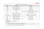
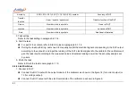
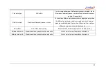
Accuracy
0.05%,0.1%,0.2%,0.5%,1%,1.5%,2%,2.5%,custom
Accuracy of DUT
Transfer
function
Linear / square / square root
Transfer function of the DUT
Owner
Numbers, letters, symbols
Owner of DUT
Location
Numbers, letters, symbols
Location of DUT
Note
Numbers, letters, symbols
Additional information
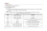
3. Task setting
Refer to the task setting in paragraph 6.1.1.4.
4. Start the task
For part of the content, refer to Start the task in paragraph 6.1.1.4.
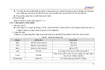
During the task performing, users need to manually control the electrical signal corresponding to the DUT output
according to the set point, and input the reading of the DUT electrical signal into the calibrator, the calibrator will
give the task result according to the measured value and entered reading as well as the accuracy analysis set
by users.
5. Finish the task
Refer to Finish the task in paragraph 6.1.1.5.
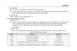
6.4.4 Limit Switches
1. Connect to DUT
Connect the DUT input with the output module of the calibrator, as shown in the figure 14 (for current output) or
13 (for voltage output).
Connect the DUT output with the electrical module of the calibrator, as shown in Figure 6.
Summary of Contents for 226
Page 1: ...226 227 Multifunction Process Calibrator...
Page 2: ......
Page 3: ...ADT226 227 Multifunction Process Calibrator User Manual Version 2306V01 Additel Corporation...
Page 4: ......
Page 6: ......
Page 31: ...19 1 4 Basic Structure Figure 1 Basic Structure...
Page 33: ...21 Figure 2 Power adaptor...
Page 64: ...52 External module information including external module A and external module B...
Page 107: ...95...


