background image


Installation Manual  
Preliminary 


Summary of Contents for Fleet One

Page 1: ...Installation Manual Preliminary...

Page 2: ...en made to ensure its accuracy Addvalue makes no warranty or representation as to the accuracy completeness or fitness for purpose or use of the information Addvalue shall not be liable for any loss o...

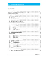
Page 3: ..._ 22 2 1 6 Installing Antenna Unit _________________________________________________ 23 2 2 Installation of BDU________________________________________________________ 24 2 3 Installation of Primary H...

Page 4: ...al A 2 ADU s Hole Pattern Cut out Holes _________________________________________ 38 A 3 BDU s Outline Dimensions _________________________________________________ 39 A 4 Primary Handset s Outline Dim...

Page 5: ...Page 5 of 39 Fleet One Terminal Installation Manual This Page Intentionally Left Blank...

Page 6: ...ause harmful interference to radio communications However there is no guarantee that interference will not occur in a particular installation If this equipment does cause harmful interference to radio...

Page 7: ...ormity with the following standards and or other normative documents ETSI EN 301 489 1 17 19 20 ETSI EN 301 444 ETSI EN 300 328 EN 60945 IEC 60950 1 AND EN 60950 1 We hereby declare that all essential...

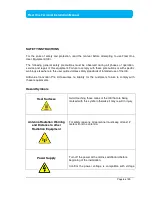
Page 8: ...ide violates safety standards of intended use of the UE Addvalue Innovation Pte Ltd assumes no liability for the customer s failure to comply with these requirements Hazard Symbols Heat Surfaces Avoid...

Page 9: ...Service Do not attempt to access to the interior of the equipment Only qualified personnel authorized by its manufacturer may perform service Failure to comply with this rule will result in the warra...

Page 10: ...of the radio spectrum To legally operate Inmarsat equipment it is necessary to obtain permission from the local telecommunications regulatory authorities of the country you are operating from Using yo...

Page 11: ...ccuracies The manual us periodically revised and updated To obtain latest version please enquire it from product manufacturer or distributor Copyright Copyright 2016 Addvalue Innovation Pte Ltd All ri...

Page 12: ...soft Windows Windows NT Windows 2000 Windows XP and Windows 7 are registered trademarks of Microsoft Corporation in the U S A and or other countries All other company and product names may be the regi...

Page 13: ...FLEET ONE ADU FLEET ONE BDU Router External Devices Above Deck Unit To be installed in an exposed area Below Deck Unit To be installed in protected area AC DC Power Supply Unit RJ45 I O Interface Nav...

Page 14: ...Fleet One BDU with Primary Handset FLV2 9TU00 01 Wideye Fleet One ADU with 15 meter Antenna Cable FLV2 0AN00 01 Fleet One Accessories Description Order Code Fleet One Primary Handset FLV2 0PH00 01 Han...

Page 15: ...mary Handset with cradle 1 2 Above Deck Equipment The ADU is a 3 axis controlled antenna unit which is self tracking The radome covers the antenna unit which is comprised of Antenna Module RF and GPS...

Page 16: ...t navigation equipment etc The BDU requires 12V or 24V DC power supply input It supplies power to the ADU via a single RF coaxial antenna cable 1 4 Wired Primary Handset with Cradle The wired Primary...

Page 17: ...Page 17 of 39 Fleet One Terminal Installation Manual The Primary Handset s connector is plugged into the BDU s primary handset port It is powered directly from the BDU...

Page 18: ...t shall be free of severe vibration and shock and heat and smoke from funnel More guidelines will be detailed in the next sections 2 1 2 Radiation Hazard Radio wave can pose hazard to human body Safe...

Page 19: ...minimum distance between a radar and the antenna unit due to different type of radars in terms of power radiation pattern and operating frequency band The antenna unit is recommended to be at least 15...

Page 20: ...ce d at 60 vertical separation 0 12 kW 0 9 m 0 5 m 30 kW 2 4 m 1 2 m 50 kW 4 0 m 2 0 m Transmitting Equipment 1GHz HF and VHF transmitters can also interfere with the performance of the antenna and al...

Page 21: ...mportant to ensure that there is a clear line of sight to the satellite for all the satellite elevation angles in the region in which the vessel will operate The antenna moves in azimuth 360 and in ro...

Page 22: ...f that Fleet One ADU An example of the antenna mast is illustrated as below and the recommendations of the antenna mast The mast should provide the internal hole for the installation of the antenna co...

Page 23: ...the ADU 2 1 6 Installing Antenna Unit The antenna unit should be carefully unpacked and checked for any damage The procedure of the installation of the antenna unit is as follow Attach the coaxial cab...

Page 24: ...cked whether they are present BDU 1 x Primary Handset with Cradle 1 x Ethernet Cable 1 x DC Power Cable 1 x Inmarsat 505 laminated card 1 x Wi Fi Antenna Hardcopy Quick Start Guide CD Format User Manu...

Page 25: ...stalled on a desktop bulkhead top ceiling or under captain s console The procedure of the installing the BDU is simple as follow Place the BDU on the desired installation area Look for the holes of th...

Page 26: ...12mm self tapping screws The procedure of the installing the cradle is simple as follow a Separate the handset from the cradle and remove the plastic cover of the cradle b Position the cradle on the...

Page 27: ...on diagram of Fleet One Terminal with the cables 12V 24V DC Input from Vessel s power distributor Bolt to vessel s hull Computer 1 5m Ethernet LAN Category 5 Cable 1 8m DC Power Cable Antenna Unit ADU...

Page 28: ...tion of the output ports of GPS and GPIO 3 1 1 GPS Output Connector The BDU has a GPS output RS 232 serial connector for outputting the GPS data in NMEA0183 format RS 232 Output Pinout Pin No Signal P...

Page 29: ...he antenna unit s transmitter GPIO 3 PDP_ON OFF To enable disable the data connection GPIO 4 BUZZER To enable external ringer buzzer for incoming call GPIO 5 GND To provide grounding for the whole sys...

Page 30: ...painting dirt grease and metal oxide at the mounting holes of the hull 4 GETTING STARTED ON THE SYSTEM 4 1 Installing the SIM card The system requires a Fleet One SIM card to access the Inmarsat s net...

Page 31: ...Page 31 of 39 Fleet One Terminal Installation Manual Push the SIM card gently until it is being clicked and locked in place Tilt down the SIM card cover to its original position SIM CARD...

Page 32: ...ators TERMINAL ANTENNA and REGSITERED to turn green LED Name Status Meaning TERMINAL Steady Amber Terminal BDU is powering up Steady Green Terminal BDU has powered up successfully Steady Red Terminal...

Page 33: ...etwork service DATA ACTIVE Steady Amber Activating data connection Steady Green Data connection is ready Steady Red Data activation failure No light Off No data connection 4 3 Settings on Web Console...

Page 34: ...ssful registration with 3 BDU s LED indicators TERMINAL ANTENNA and REGSITERED which are in green the terminal will be ready for normal operation 4 3 2 Activating PDP Context To activate the PDP conte...

Page 35: ...f 39 Fleet One Terminal Installation Manual 4 3 3 Deactivating PDP Context To deactivate the PDP context for browsing internet click Deactivate Data Connection The BDU s LED indicator DATA ACTIVE will...

Page 36: ...Point Name BDU Below Decks Unit DC Direct Current FTP File Transfer Protocol GPS Global Position System GPIO General Purpose Input Output IP Data Internet Protocol Data NAT Network Address Translation...

Page 37: ...Page 37 of 39 Fleet One Terminal Installation Manual APPENDIX A OUTLINE DRAWINGS A 1 ADU s Outline Dimensions and Weight Weight 3 2 kg Dimensions are expressed in terms of mm...

Page 38: ...Page 38 of 39 Fleet One Terminal Installation Manual A 2 ADU s Hole Pattern Cut out Holes Dimensions are expressed in terms of mm...

Page 39: ...e Terminal Installation Manual A 3 BDU s Outline Dimensions A 4 Primary Handset s Outline Dimensions Weight 3 1kg Dimensions are expressed in terms of mm Weight 430g including cradle Dimensions are ex...

Reviews: