
Switch off Mains Supply to the Controller
Remove outer cover panel by removing the green hole plug in the cover, undo the screw, remove cover by
unhooking it, undo the inner cover screw and remove the inner cover.
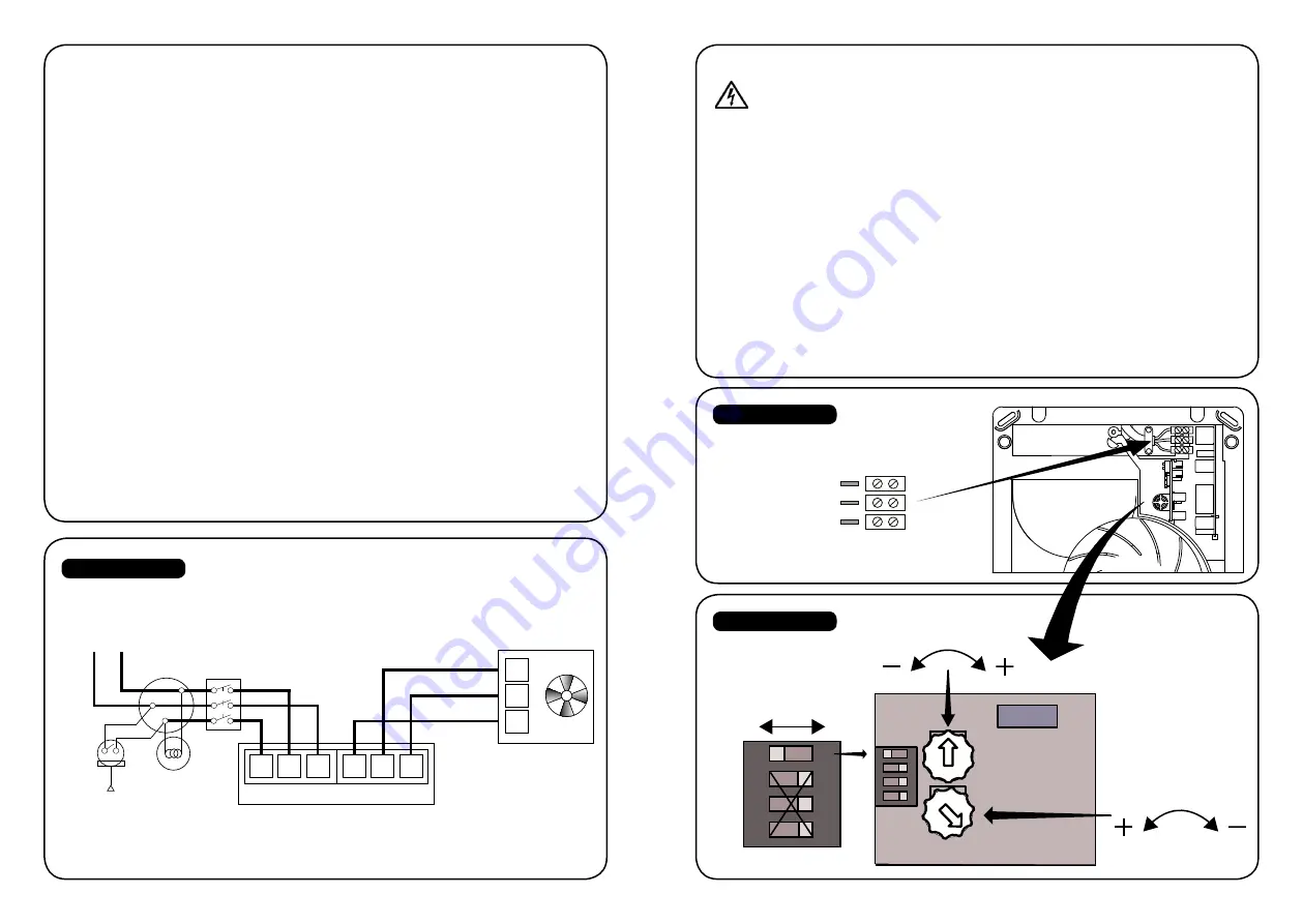
The smaller Printed Circuit Board has the adjusters on it - see diagram 2 below.
Boost Speed - High or Low - Activated by the Pullcord Switch, Switched Live or Humidity
Slide the top switch to the left for High Speed, to the right for Low Speed.
Humidity Set Point - This will boost the fan from constant trickle to the selected boost speed.
Using a small screwdriver gently rotate the lower adjuster wheel anti clockwise to lower the humidity
level that will make the fan switch from trickle to boost speed, clockwise to raise the level.
Run On Time - This sets the length of time that the fan will continue to run on boost after the Pullcord /
Switched Live or Humidity activation is switched off.
Using a small screwdriver gently rotate the upper adjuster wheel anti clockwise to reduce the time and
clockwise to increase the time.
Green LED - The Green LED will remain on, while either the: Pullcord Switch or Switched Live are
turned on or Humidity Set Level is exceeded. When these are turned off the LED will turn off, the fan will
continue to run on boost until the run on time limit is reached.
0 VDC
12 VDC
12 VDC - SWITCHED
SURFACE FITTING
Select a suitable position for the fan and
cut the 112mm diameter hole for the
discharge duct.
1. Mark the position on the wall for the 255mm
high x 205mm wide surface mounted box, hold
in position and mark the four fixing holes. Care
must be taken to ensure the discharge hole is
the correct orientation to suit the fan when
fitted.
2. Drill and plug the four fixing holes and screw
the surface mount box to the wall (care must
be taken not to over tighten the screws).
3. Bring the power cable into position and ensure
that you allow extra cable protruding to
facilitate connection.
4. Remove the front cover of the fan by first
removing the cover fascia (one screw located
at the top behind the green hole plug – remove
this by gently prying it out with a fine tipped
screwdriver) and then removing the fixing
screw located at the bottom, the cover then
clips off. The chassis is fixed to the surface
mount box by four screws. See diagram 2 for
wiring connections.
RECESSED/FLUSH FITTING
Select a suitable position for the fan and
cut a hole to suit the outlet and a recess
to suit the body of the fan.
1. Vertical Discharge (Usually in the stud work
internal walls) 225mm high x 180mm wide x
120mm deep
2. Horizontal Discharge (Usually cavity external
walls) 225mm high x 180mm wide x 75mm
deep.
3. Position of Discharge hole Care must be taken
to ensure the 112mm discharge spigot is the
correct orientation to suit the recess. Always
check studwork walls to ensure the hole and
recess are between vertical timber studs
• Bring the power cable into position and ensure
that you allow extra cable protruding to
facilitate connection.
• Hold the chassis in the recess and mark the
position of the fixing holes. Drill and plug the
four fixing holes and screw the chassis into
position.
• Refer to Diagram 1 & 2 for wiring connections.
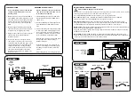
DIAGRAM 1
DIAGRAM 2
BOOST SPEED SELECT
HIGH
LOW
OVER RUN TIMER
HUMIDITY SET POINT
Adjusting the
fan’s settings
1 2 3 4
ON DIP
DIAGRAM 3
ADJUSTING THE FANS SETTINGS
LAMP
PULLCORD
SELV SUPPLY
(12V DC)
3 POLE
ISOLATOR
SWITCH
CEILING
JUNCTION
MAINS
SUPPLY
220-240 VAC
50Hz
L
~
N
Ls
L
12v
Ls 0v
CONTROLLER
N
FAN
Ls
12v
0v
12 VDC LIVE SWITCHED
0 VDC
12 VDC


