129
【
9
】
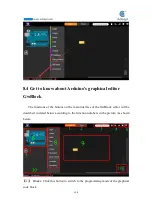
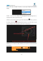
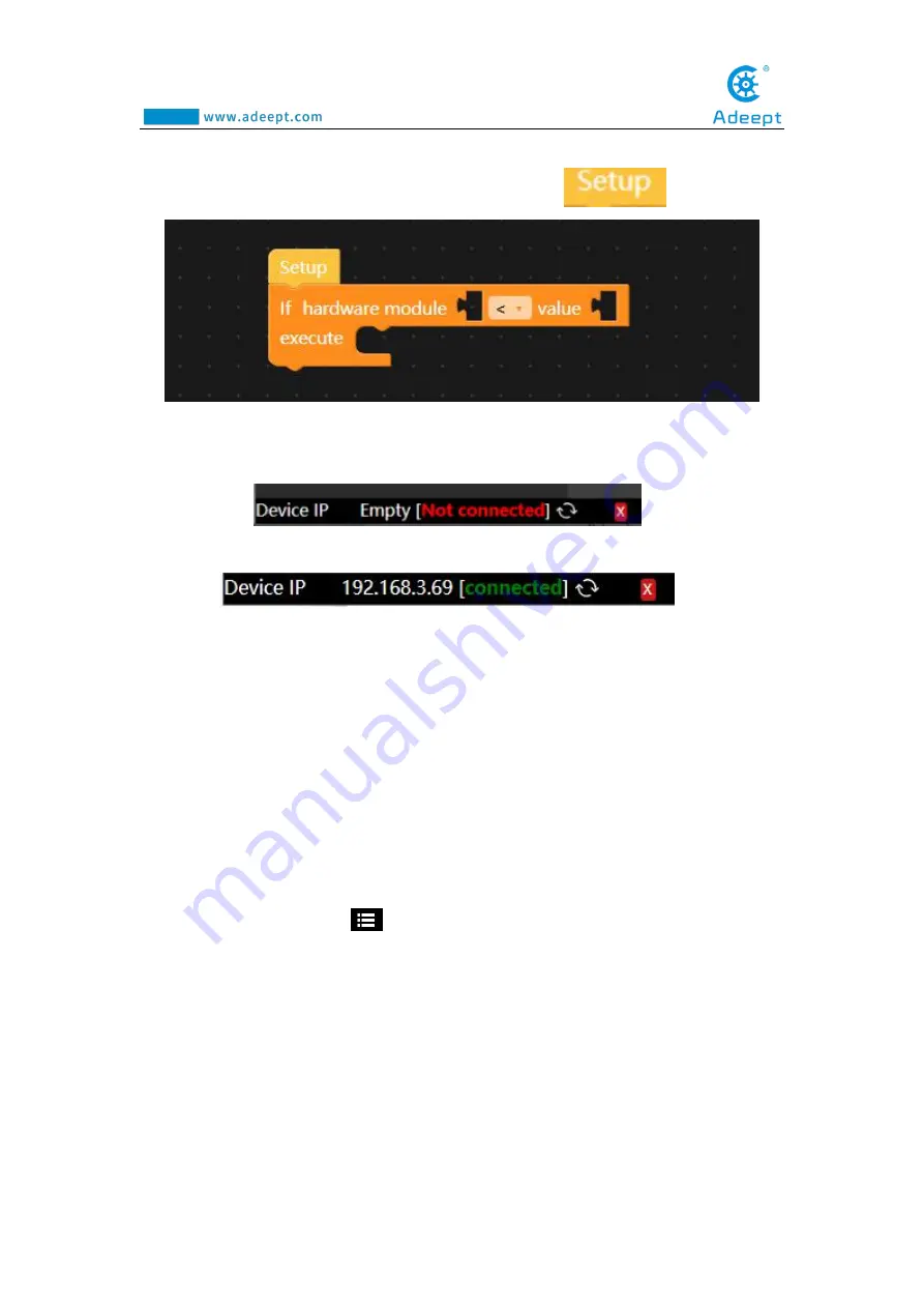
is the editing area (code area or work area), where we edit the code instruction
block. Each code instruction block must be placed below
.
【
10
】
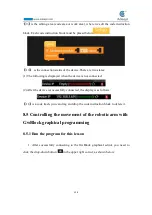
is the connection status of the device.There are two states:
(1) The following is displayed when the device is not connected:
(2) After the device is successfully connected, the display is as follows:
【
11
】
is a code trash, you can drag and drop the code instruction block to delete it.
8.5 Controlling the movement of the robotic arm with
GwBlock graphical programming
8.5.1 Run the program for this lesson
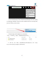
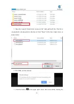
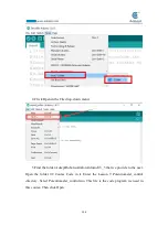
1. After successfully connecting to the GwBlock graphical editor, you need to
click the drop-down button
in the upper right corner, as shown below:
Summary of Contents for Robotic Arm
Page 1: ...1...
Page 33: ...30 9 Running effect is as follow...
Page 74: ...71 SERVO of number 5 4 2 1 3...
Page 86: ...83 Effect diagram after assembling...
Page 95: ...92 40mm 60mm 66 5mm 65mm 13mm 70mm...
Page 99: ...96...
Page 111: ...108...
Page 137: ...134...
Page 154: ...151 7 the library file controlP5 needs to be added...
Page 156: ...153 9 Click Run 10 Running effect is as follow...
Page 164: ...161...
Page 181: ...178...
Page 182: ...179...

