87
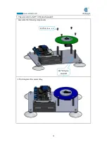
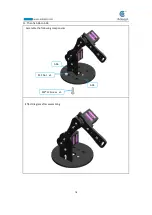
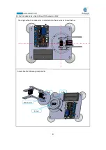
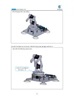
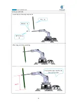
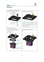
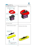
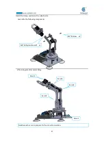
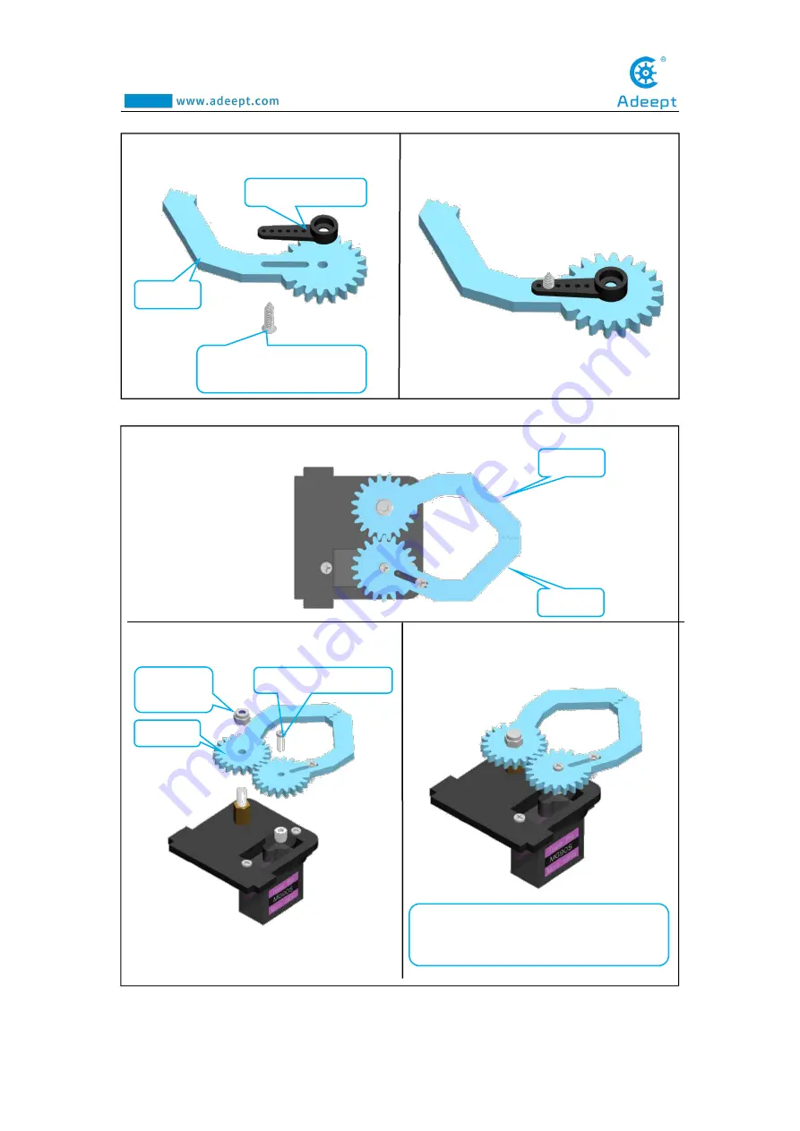
Assemble the following components
Effect diagram after assembling
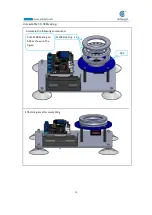
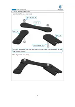
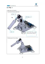
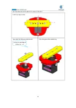
Install A16 and A17 as shown below.
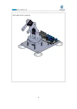
Effect diagram after assembling
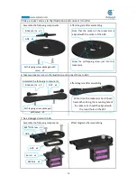
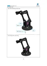
Assemble the following components
3. Fix one rocker arm of the servo to A17.
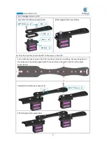
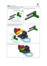
4. Assemble A16 and A17.
A17 x1
Rocker arm x1
Self-tapping screw packaged
with servo
x1
A16
A17
M2.5*7 Screw x1
M3 Lock
Nut x1
A16 x1
Do not tighten the M3 Lock Nut to ensure
that the A16 can rotate.
Summary of Contents for Robotic Arm
Page 1: ...1...
Page 33: ...30 9 Running effect is as follow...
Page 74: ...71 SERVO of number 5 4 2 1 3...
Page 86: ...83 Effect diagram after assembling...
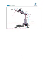
Page 95: ...92 40mm 60mm 66 5mm 65mm 13mm 70mm...
Page 99: ...96...
Page 111: ...108...
Page 137: ...134...
Page 154: ...151 7 the library file controlP5 needs to be added...
Page 156: ...153 9 Click Run 10 Running effect is as follow...
Page 164: ...161...
Page 181: ...178...
Page 182: ...179...

