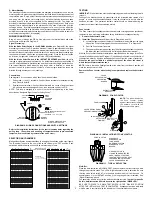
Selecting a Mounting Location:
The detector responds to changes in energy which occur when an intruder moves into
or out of a protective zone. Best coverage will be obtained if the mounting site is
selected such that the likely direction of intruder motion is ACROSS the pattern.
Passive I.R. units are remarkably resistant to false alarm hazards, but the following
recommendations should be observed:
Install the detector at a height of approximately 7 feet (2.1m)
from floor. Do not mount on an unstable surface.
IMPORTANT! Avoid running alarm wiring close to heavy-
duty electrical power cables.
Do not install where the detector is exposed to direct sunlight
or directly above strong sources of heat.
Avoid locating a unit in areas which contain objects likely to
produce a rapid change in temperature, such as central
heating, radiators or ducts (or heaters of any kind), air
conditioners, open flame, etc.
Make sure the detection area does not have obstructions
(curtains, screens, large pieces of furniture, plants, etc.)
which may block the pattern of coverage.
INSTALLATION
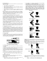
A. Changing From Wide Angle to Long Range Coverage:
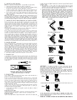
1. Remove front cover by inserting a screwdriver blade in the groove between cover
and base at one of the locations shown in Diagram 3, rotating the blade to override
snap fit, and then lifting cover off.
2. Spread either or both plastic prongs holding the wide angle (12.2m) mirror and
remove the mirror (Diagram 4).
3. Insert one side of the long range (24.4m) mirror under a prong and snap the other
side under the other prong. Make sure that the mirror sides are squarely in their
corner rests and are held securely under the prongs.
NOTE: Mirror surface should be free of dirt, foreign matter and fingerprints. Use a clean
dry soft cloth to wipe mirror surfaces, if required.
LIFT
COVER
2
1
INSERT SCREWDRIVER
AT LOCATION a, b or c
AND TWIST
c
a
b
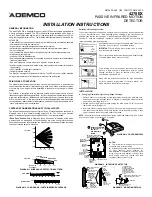
GENERAL INFORMATION
The No. 4278EX PIR is designed for use only with VISTA series systems equipped with
a 2-wire polling loop interface. The PIR provides wide angle coverage with a range of
up to 12.2m using the wide angle mirror, or long range/curtain coverage of up to 24.4m
using the long range/curtain mirror. The following important features are included in the
4278EX PIR:
• Quad element pyroelectric sensor providing the reliability of two completely separate
dual detectors covering the same area.
• High precision, computer designed parabolic optical system.
• Horizontally adjustable optical system for accurate aiming of protection pattern.
• Pulse count option.
• Low current drain which allows for direct powering from the multiplex polling loop.
• Wall/corner mounting plate.
• Walk-test LED with disable switch.
• Dual channel signal processing for enhanced immunity to environmental disturbances
(reduced false alarms).
• Two wire interface to control - power and signal on same wire pair.
• Auxiliary sensor loop permits interface of any other nearby alarm sensor (for example,
reed contact).
• 100% rejection of visible light interference.
• Tamper protected housing.
The detector is designed to operate at all times. The LED on the unit will be disabled
during normal operation to limit the power drawn from the polling loop.
PRINCIPLES OF OPERATION
The optical system divides the area into a series of protected zones. A quad element
sensor measures the level of infrared energy in each zone. When an intruder crosses
or enters any zone, a signal will be generated in response to the change in infrared
energy.
The detector is configured with an alternate polarity quad element sensor and two
independent signal processing amplifiers. In effect, two passive infrared sensors share
a common optical system. Both sensors must detect motions at the same time for the
PIR to report an alarm. In this way, immunity is provided against false alarms attributed
to channel noise, random detector disturbances, and power supply line transients, while
“catch” performance is not compromised.
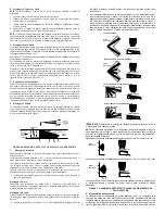
COVERAGE CONSIDERATIONS AND TYPICAL LAYOUTS
The range will depend upon the mirror system in use. Protective patterns are shown in
Diagrams 1 and 2 for a normal mounting height of 2.1m. The unit may be mounted
higher for increased range but mounting above 2.6m is not recommended.
“Dead Zone” Caution: Note in Diagram 1 that a “dead zone” is indicated, within which
a person could be moving and not be detected by any of the unit’s protective zones.
Other dead zones may occur between the detector and the downward fields of view as
the unit’s mounting height is increased.
®
4278EX
PASSIVE INFRARED MOTION
DETECTOR
INSTALLATION INSTRUCTIONS
6.1m
3.0m
0
3.0m
6.1m
3.0m 6.1m 9.1m 12.2m
3.0m 6.1m 9.1m 12.2m
APPROX. 1.2m
DEAD ZONE
2.1m
0
DETECTOR
DOWNWARD
INTERMEDIATE
MAIN
TOP VIEW
SIDE VIEW
2.3m
3.0m 12.2m 24.4m
TOP VIEW
DIAGRAM 1. WIDE ANGLE PROTECTION PATTERN
DIAGRAM 2. LONG RANGE / CURTAIN MIRROR COVERAGE
0.7m 24.4m
SIDE VIEW
2.1m
See Diagram 4,
Note B.
INSERT SMALL SCREWDRIVER
TO RELEASE WALL PLATE
INTERLOCKING SPRING TAB
WIRING ENTRY
NOTCH (IN BOARD)
AND PASSAGE
(IN BASE)
PC BOARD
MOUNTING
TABS (2)
PC BOARD
SUPPORT
POSTS (2)
PLASTIC PRONG (2)
(HOLD MIRROR
IN PLACE)
HORIZONTAL
ADJUSTABLE
MIRROR
CARRIER
MIRROR WIDE ANGLE
MIRROR
CORNER
RESTS (4)
TERMINAL
BLOCK
LED
DIAGRAM 3. COVER REMOVAL
DIAGRAM 4. INTERIOR OF DETECTOR
MOUNTING SURFACE
HOOKS (2)
WIRE ENTRY AREA
SEE DETAIL "A"
SLOTS (4)
ENGAGE SLOTS
ONTO HOOKS
AND SLIDE
HOUSING BASE
DOWN FIRMLY
WALL
PLATE
EARS (4) FOR
CORNER
MOUNTING
(MAY BE
BROKEN OFF
IF MOUNTED
ON FLAT WALL)
CIRCUIT
BOARD
SUPPORT
POSTS (2)
CIRCUIT
BOARD
MOUNTING
TABS (2)
HOUSING
BASE
(COVER
REMOVED)
HOOKS (2)
C
L
IRCUIT
OARD
UPPORT
OSTS (2)
TABS (2)
FOR CONCEALED
WIRING, CUT A 8mm
DIAMETER (MAX) WIRING
HOLE IN MOUNTING
SURFACE. CENTER OF
HOLE MUST BE ON LINE
WITH TOP EDGE OF WALL
PLATE.
INTERLOCKING TAB ENTERS CUTOUT
IN BASE-LOCKS BASE TO PLATE
HOLE (3) FOR MOUNTING
THE PLATE TO WALL
DETAIL A
C
L
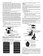
DIAGRAM 5. MOUNTING DETAILS
NOTES:
A. Thin exterior wal in wiring entry area can be
cut/broken away for surface wiring.
B. Hole along upper edge of housing permits use
of cover securing screw (required for
VDS/Skafor/ANPI compliance) and holes within
wiring entry area perit addition of wiring clamp.
Keep housing screw hole covered (with label
supplied or tape) if screw not used.
2.1m
APPROX
N4756-7ENV3 1/99
PART OF N4756-7V3

