Installation Hints
•
Never install the detector in an environment that causes an alarm condi-
tion in one technology. Good installations start with the LED OFF when
there is no target motion. It should never be left to operate with the tri-
color LED in a constant or intermittent green, yellow, or red condition.
•
Point the unit away from outside traffic (roads/alleys). Remember: Mi-
crowave energy will pass through glass and most common non-metallic
construction walls. Avoid installations where rotating machines (e.g., ceil-
ing fans) are normally in operation within the coverage pattern.
•
Point the unit away from glass exposed to the outdoors and objects that
may change temperature rapidly. Remember: The PIR detector will
react to objects rapidly changing temperature within its field-of-view.
•
Eliminate interference from nearby outside sources.
Special Instructions
for Installations Containing Pets
The QUEST 2135 will provide reasonable protection from nuisance
alarms caused by the following sources:
•
A dog up to 100 pounds.
•
Two dogs, up to 60 pounds each.
•
Up to 10 cats.
•
Multiple small rodents, such as rats.
•
Random flying birds.
To take full advantage of the QUEST 2135’s Pet Exclusion Technology,
the following guidelines should be followed:
•
Mount the center of the detector 6-1/2 feet high and adjust the vertical
angle to -5°.
•
Set the PIR sensitivity for standard (STD).
•
Mount where animals cannot come within six feet of the detector by
climbing on furniture, boxes, or other objects.
•
Do not aim the detector at stairways that can be climbed by an animal.
•
Adjust the microwave range for the minimum acceptable coverage for
the room in which the detector is installed. Never install with the micro-
wave range exceeding 35 feet.
NOTE:
This nuisance protection has not been verified by Underwriter’s
Laboratories, Inc.
QUEST 2135-INST 12/97
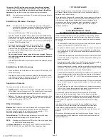
Figure 1. Coverage Pattern
Figure 2. Interior View
QUEST 2135
Microwave/PIR Intrusion Detector
Specifications
Input Power:
9 to 15 VDC, 16 mA DC nominal (up to 48 mA DC during
walk testing or trouble conditions).
Standby Power:
No internal standby battery. Connect to DC power sources
capable of supplying standby power. Sixteen mA-H re-
quired for each hour of standby time needed.
Alarm Relay:
Silent operating Normally Closed reed relay. Contacts rated
3 watts, 125 mA, 28 VDC maximum for DC resistive loads,
and protected by a 4.7 ohm, 1/2 watt resistor in the com-
mon “C” leg of the relay.
Do not use with capacitive or
inductive loads.
Operating
Temperature:
-40° to +120°F (-40° to +49°C). For U.L. Listed Require-
ments, the temperature range is +32° to +120°F (0° to
+49°C).
Microwave
Frequency:
10.525 Ghz ± 25 MHz
Coverage:
35 ft. by 35 ft. (10.7 m by 10.7 m)
Internal
Pointability:
+2° to –10° Vertical, ±10° Horizontal.
Tamper:
Normally Closed (with cover on). Contacts rated at 28 VDC,
0.125 A max. Connect tamper circuit to 24 hour protection
circuit.
Options:
QUEST SB2 swivel bracket. (Use of a bracket may re-
duce range and dead zone area).
NOTE:
The protected coverage area is where the microwave and PIR
patterns overlap.
NOTE:
To use the optional Look Down Zone, the Mask must be removed
from the Look Down Lens. Use caution to remove the black
mask only. Do not attempt to remove the white lens assembly.
Do not remove the Mask for pet applications. See Figure 2.
www.PDF-Zoo.com


