Ð 2 Ð
OPTIMIZING PET IMMUNITY
The Rx4GLD provides reasonable protection from nuisance alarms
caused by pets or animals up to 45 pounds if the following guidelines
are followed:
¥ Mount the center of the detector at 7 feet high.
¥ Set the sensitivity to Standard (STD) and Normal.
¥ Mount where animals cannot come within 6 feet of the detector
by climbing on furniture, boxes or other objects.
¥ Do not aim the detector at stairways that can be climbed by the
animal.
WALL OR CORNER MOUNTING
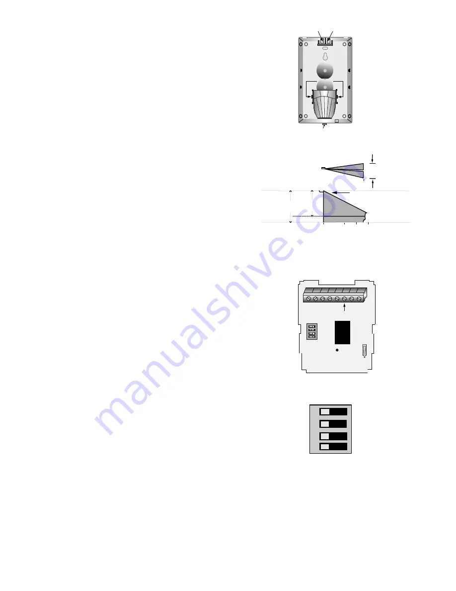
Mount the unit to a firm vertical surface. The wall wiring hole should
be no more than 5/16" (8mm) diameter.
1. Remove the front cover and PC board.
2. Referring to Figure 2, break out the desired knockout mounting
holes. Use knockout holes "A" for normal surface mounting. Use
knockout holes "B" for corner mounting. Break out the desired
wire entry hole marked X1 or X2 at the top of the detector base.
3. Feed wiring emerging from the wall through the wire access hole.
4. Mount the base and reinstall the PC board.
5. Refer to WIRING CONNECTIONS section before replacing the
cover.
OPTIONAL CEILING MOUNTING
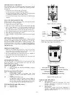
The versatility of this detector permits optional ceiling mounting,
using the Long Range/Curtain mirror. This provides a 15-20ft (4.5-
6m) forward-looking curtain pattern as shown in Figure 3. The
mounting procedure is the same as for "Normal Wall Mounting,"
except that the unit is ceiling mounted,
with the unit facing toward
the detection area
.
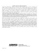
WIRING CONNECTIONS
1. Bring all wires through the wire access slot at the top of the
detector base near the terminal block, and connect to the screw
terminal. See Figure 4 for terminal designations.
2. Seal any openings in the base with foam or RTV (not supplied) to
prevent drafts and insects from entering the unit.
3. Apply power only after all connections have been made and
inspected.
DIP SWITCH SETTINGS
Use the DIP switch to select Walk Test/ Normal mode and Pulse
Processing options. Use a small pointed tool to move the switch
handles OFF or ON as desired.
Normal/ Walk Test Mode: DIP position 1
OFF
=
Normal Mode
ON
=
Walk Test Mode (See TEST PROCEDURES section for
description)
Pulse Processing Option: DIP position 2
OFF
=
Standard Pulse Processing
Recommended setting for maximum false alarm
immunity. It tolerates environmental extremes on this
setting.
ON
=
Intermediate Pulse Processing
Recommended setting for locations where an intruder is
expected to cover only a small portion of the protected
area. It tolerates normal environments on this setting.
Use this setting with the Long Range/Curtain mirror.
LED Enable/Disable Option: DIP position 3
OFF
=
Enable the LED
ON
=
Disable the LED
Prongs
A
A
B
B
X1
X2
A
A
B
B
Insert screwdriver
at this end to open.
Figure 2. Back Case with Mirror
CEILING
CEILING
HEIGHT
FLOOR
➪
12'
(3.6m)
FLOOR
10'
(3m)
0
10'
(3m)
15'
(4.6m)
20'
(6m)
Mount unit so that
PIR window is towards
detection area
SIDE
VIEW
18'
(5.5m)
4'
(1.2m)
TOP
VIEW
(at 12 ft
(3.6m)
ceiling
height)
Figure 3. Detection Area with Ceiling Mounted
Unit Using Long Range (Curtain) Mirror
+
–
}
NC
C
}
9-16VDC
INPUT
ALARM
RELAY
TROUBLE
OUTPUT
LED
DIP Switch
MICRO
NO
}
TAMPER
TAMPER
SWITCH
Figure 4. Wiring Details
1
2
3
4
OFF
ON
Normal Operation
Standard Processing
LED Enabled
Normal Sensitivity
Walk-Test Mode
Intermediate Processing
LED Disabled
High Sensitivity
Figure 5. DIP Switch Functions
Sensitivity Option: DIP position 4
OFF
=
Normal Sensitivity
Recommended setting for maximum false alarm
immunity. Maximum environmental extremes are
tolerated on this setting.
ON
=
High Sensitivity
Recommended setting when ambient temperature is
expected to approach the temperature of the human body
(approximately 90
°
F/32
°
C).


