background image


– 7 – 

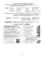
RESTORE REPORT CODES (

70 – 

76) 


70  ALARM RESTORE RPT CODE


[0] 


2nd digit is automatically sent as the 2nd digit of 
the zone alarm report code programmed in 

56, 

if expanded or 4+2 reporting is selected. 

71  TROUBLE RESTORE RPT CODE


[00] 

    |    


72  BYPASS RESTORE RPT CODE


[00] 

    |      

73  AC RESTORE RPT CODE 

[00] 

    |    


74  LOW BAT RESTORE RPT CODE 

[00] 

    |    


75  RF XMTR LO BAT RST RPT CODE


[00] 

    |    


76  TEST RESTORE RPT CODE 

[00] 

    |    


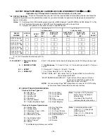
DAYLIGHT SAVING TIME (

77 – 

78)   

 DYNAMIC SIGNALING (

79)


77  DAYLIGHT SAVING TIME 

[4,10] 

    |      


 START/END 

MONTH


0 = Disabled; 1 = Jan; 2 = Feb; 3 = Mar…. 


10 = Oct; 11 = Nov; 12 = Dec. 


(Enter 0-9); #+10 = 10; #+11 = 11; #+12 = 12 


78  DAYLIGHT SAVING TIME 

[1,5] 

    |      


 START/END 

WEEKEND


0 = Disabled; 1 = First; 2 = Second; 3 = Third; 


4 = Fourth; 5 = Last; 6 = Next to Last; 


7 = Third to Last 


1st Entry 

2nd Entry 

79 DYNAMIC SIGNALING 

[0] 


 [0] 


† 


DS Delay 

DS Priority 


D S Delay;   0-15 times a 15-sec delay 


1 = 15 secs; 2 = 30 secs; 3 = 45 secs; 


4 = 60 secs…etc. 


0 = No delay. (Reports are sent to both  


the Primary Phone No. and LRR). 


For UL installations, set for 0 = No delay 


D S Priority;   0 = Send message to Primary  


Phone No. first; 


1 = Send message to LRR first.


†  

Entry of a number other than the one specified will give unpredictable results. 


OUTPUT AND SYSTEM SETUP (

80 – 

93) 

80  OUTPUT RELAYS AND 

POWERLINE CARRIER 
DEVICES 

81  ZONE LISTS FOR OUTPUT 

DEVICES


Program only if 
Relays and/or 
Powerline Carrier 
devices are to be 
used. See page 9. 

82 

CUSTOM ALPHA EDITING 

(

Also entered from field 

56) See procedure in instructions. 

84 

AUTO STAY ARMING 


[0] 


0 = no;  1 = yes 

85 

CROSS ZONE TIMER (in seconds)


[0] 


0 = 30 


1 = 45 


2 = 60 


3 = 90 


4 = 120 


5 = 180 


6 = 240 


NOTE: This field (

85

) and Zone List 04 are not to be 

used in UL installations. 

87 

ALARM PAGER DELAY TIME


[3] 


0 = none 


1 = 1 minute 


2 = 2 minutes 


3 = 3 minutes 

88 PAGER 

CHARACTERS


(16 digits as user decides)


   |   |   |   |   |   |   |   |   |   |   |   |   |   |   |   |


(See field 

41 for programming instructions) 

89  EVENT LOG 80% FULL RPT CODE 

[00]  

    |    


90 

EVENT LOGGING 

[3]  


0 = None; 1 = Alarm/Alarm Restore;  
2 = Trouble/Trouble Restore;  4 = Bypass/Bypass 
Restore; 8 = Open/Close. 


Example:  To select “Alarm/Alarm Restore” and 
“Open/Close,” enter 9 (1 + 8); to select all, enter #+15. 


Note:  System messages are logged when any 
non-zero selection is made. 

91 

OPTION SELECTION (AAV) 

[8]


0 = None; 


4 = AAV;  


8 = Enable Exit Delay Restart; 


12 = Both enabled. 


0 for UL installations. 

92 

PHONE LINE MONITOR ENABLE 

[0] 


0 = Not used 


1 = Keypad display when line is faulted 


2 = Keypad display  plus keypad trouble sound 


3 = Same as “2,” plus Device #2 STARTS. If armed, 
external sounder activates also. 


Note: Device #2 must either be programmed to be  


STOPPED in field 

80 or STOPPED by  


Code + # + 8 + 2. 

93 SWINGER 

SUPPRESSION 

[0]


0 = Unlimited; 1 - 15 = Number of Alarms 


(0 - 9; #+10 = 10; #+11 = 11; #+12 = 12;  


#+13 = 13; #+14 = 14; #+15 = 15) 


0 for UL installations. 


Summary of Contents for Security System VISTA-15

Page 1: ...K3894V2 7 01 9 67 9 67 1 6HFXULW 6 VWHP 3URJUDPPLQJ XLGH...

Page 2: ...2...

Page 3: ...T TO LONG RANGE RADIO 0 0 disable enable Trouble code 1 9 B 11 C 12 D 13 E 14 or F 15 The 2nd digit of Trouble Dialer Report is automatically entered from field 60 0 for UL installations 30 HARDWIRE S...

Page 4: ...3 1 4 1 ADEMCO L S STANDARD 1 3 1 4 1 RADIONICS STANDARD 2 4 2 ADEMCO L S STANDARD 3 4 2 RADIONICS STANDARD 6 or undefined 4 2 ADEMCO EXPRESS 7 ADEMCO CONTACT ID REPORTING 8 3 1 4 1 ADEMCO L S EXPANDE...

Page 5: ...ss 9 2 01 00 Keypad Panic 1 9 5 00 01 00 Keypad Panic 3 9 6 00 01 00 Keypad Panic 9 9 07 01 00 EXPANSION ZONES Assign zone numbers Zn 10 17 to 4219 4229 Auxiliary Wired Loops A H if used ENTER FOR RF...

Page 6: ...INPUT Used with 5800 RF Loop Input Devices Record transmitter input number SYSTEM STATUS REPORT CODES 59 68 TO PROGRAM SYSTEM STATUS RESTORE REPORT CODES 59 76 89 With a 3 1 or 4 1 Standard Format Ent...

Page 7: ...DEVICES 81 ZONE LISTS FOR OUTPUT DEVICES Program only if Relays and or Powerline Carrier devices are to be used See page 9 82 CUSTOM ALPHA EDITING Also entered from field 56 See procedure in instruct...

Page 8: ...er of rings 1 9 10 10 11 11 12 12 13 13 14 14 15 answering machine defeat 15 15 Note Do not enter 0 if using 4285 4286 Voice Module 96 INITIALIZES DOWNLOAD ID SUBSCRIBER ACCOUNT NO FOR INITIAL DOWNLOA...

Page 9: ...r 2 sec 2 Close and stay closed 3 Pulse on and off EV EVENT 0 Not used 1 Alarm 2 Fault 3 Trouble Z L ZONE LIST 1 2 or 3 from Field 81 or 0 Not Used START ZONE LIST Upon alarm fault or trouble of ANY z...

Page 10: ...Started or stopped by zone numbers enter 00 to end entries etc Zone List 03 Started or stopped by zone numbers AND OR assignment of Chime zones enter 00 to end entries etc Zone List 04 Cross Zone lis...

Page 11: ...rol to clear this indication and remove the disable indication TO ENTER PROGRAMMING MODE 1 POWER UP then press and both at once within 50 seconds of powering up OR 2 Initially key Installer Code 4 1 1...

Page 12: ...EATION 159 REFRIGERATION 160 RF 161 RIGHT 162 ROOM 163 ROOF S 164 SAFE 165 SCREEN 166 SENSOR 167 SERVICE 168 SHED 169 SHOCK 170 SHOP 171 SHORT 173 SIDE 174 SKYLIGHT 175 SLIDING 176 SMOKE 178 SONS 179...

Page 13: ...13 ENROLLED TRANSMITTERS ZONE No ZONE TYPE ZONE INPUT TYPE SERIAL No If applicable Stick Serial No Label from Transmitter Here LOOP No DEVICE LOCATION...

Page 14: ...14 ENROLLED TRANSMITTERS cont d ZONE No ZONE TYPE ZONE INPUT TYPE SERIAL No If applicable Stick Serial No Label from Transmitter Here LOOP No DEVICE LOCATION...

Page 15: ...OR 700 MSEC PROGRAMMABLE VISTA 15 VISTA 15CN SUMMARY OF CONNECTIONS USE UL LISTED LIMITED ENERGY CABLE FOR ALL CONNECTIONS BATTERY FUSE FOR REPLACEMENT USE SAME VALUE e g ADEMCO No 90 12 9 PIN CONNEC...

Page 16: ...165 Eileen Way Syosset New York 11791 Copyright 2000 PITTWAY CORPORATION 9 V K3894V2 7 01 See Instructions K3892V2...

Reviews: