VISTA-50PEN Installation and Setup Guide
18-4
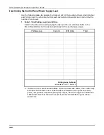
Determining the Control Panel Power Supply Load
Use the following tables to calculate the total current for the Auxiliary Power, Alarm Output
and Polling Loop. In each table, multiply each device's standby and/or alarm current by the
number of units used.
1. Table 1: Total Polling Loop Current Draw
Refer to the instruction accompanying the device for the current draw. Refer to the
POLLING LOOP section for device restrictions for fire and burglary usage.
Polling Loop
Current
# of Units
Total
Polling Loop Subtotal
(terminals 24 & 25 – 128mA)
✳
✳
The total current cannot exceed 128mA. If total load exceeds 128mA, then a 4297 loop
Extender Module can be used. This module is powered from the panel's auxiliary
power, and provides a separate polling loop output, which can support an additional
128mA load. Note that the total number of points connected to the panel cannot
exceed 119.
Summary of Contents for VISTA-50PEN
Page 2: ...ii...
Page 10: ...VISTA 50PEN Installation and Setup Guide x...
Page 26: ...VISTA 50PEN Installation and Setup Guide 3 4...
Page 42: ...VISTA 50PEN Installation and Setup Guide 6 6...
Page 56: ...VISTA 50PEN Installation and Setup Guide 8 8...
Page 82: ...VISTA 50PEN Installation and Setup Guide 13 4...
Page 110: ...VISTA 50PEN Installation and Setup Guide 18 8...
Page 118: ...VISTA 50PEN Installation and Setup Guide 20 4...
Page 138: ...VISTA 50PEN Installation and Setup Guide 22 18...
Page 166: ...VISTA 50PEN Installation and Setup Guide 25 6...
Page 172: ...VISTA 50PEN Installation and Setup Guide 27 2...
Page 186: ...VISTA 50PEN Installation and Setup Guide 29 8...
Page 192: ...VISTA 50PEN Installation and Setup Guide 30 6...
Page 197: ...B 1 A P P E N D I X B DIP Switch Tables...
Page 200: ...VISTA 50PEN Installation and Setup Guide B 4...
Page 214: ...l K3271 1BX 9 00 165 Eileen Way Syosset NY 11791 Copyright 2000 PITTWAY Corporation...

