Section 18 – Final Power-Up Procedure
18-5
2.
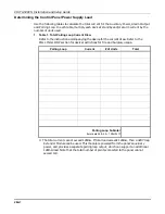
In table 2, enter devices used on Auxiliary Power. Calculate standby and alarm currents,
then add to get Auxiliary Power current subtotal.
Table 2: Auxiliary Power Current Load
Total Current
Device Model #
Device Current X # of Units =
Standby
Alarm
Auxiliary Power Subtotal
(terminals 6 & 7 – 750mA max.)
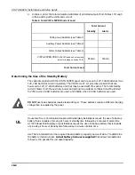
3.
In table 3, enter devices connected to the Alarm Output. Calculate alarm currents, then
add to get the Alarm Output current subtotal.
Table 3: Alarm Output Current Load
Total Current
Device Model #
Device Current X # of Units =
Standby
Alarm
XXXXXX
XXXXXX
XXXXXX
XXXXXX
XXXXXX
XXXXXX
XXXXXX
Alarm Output Subtotal
(terminals 4 & 5 - 1.7A max.)
Summary of Contents for VISTA-50PEN
Page 2: ...ii...
Page 10: ...VISTA 50PEN Installation and Setup Guide x...
Page 26: ...VISTA 50PEN Installation and Setup Guide 3 4...
Page 42: ...VISTA 50PEN Installation and Setup Guide 6 6...
Page 56: ...VISTA 50PEN Installation and Setup Guide 8 8...
Page 82: ...VISTA 50PEN Installation and Setup Guide 13 4...
Page 110: ...VISTA 50PEN Installation and Setup Guide 18 8...
Page 118: ...VISTA 50PEN Installation and Setup Guide 20 4...
Page 138: ...VISTA 50PEN Installation and Setup Guide 22 18...
Page 166: ...VISTA 50PEN Installation and Setup Guide 25 6...
Page 172: ...VISTA 50PEN Installation and Setup Guide 27 2...
Page 186: ...VISTA 50PEN Installation and Setup Guide 29 8...
Page 192: ...VISTA 50PEN Installation and Setup Guide 30 6...
Page 197: ...B 1 A P P E N D I X B DIP Switch Tables...
Page 200: ...VISTA 50PEN Installation and Setup Guide B 4...
Page 214: ...l K3271 1BX 9 00 165 Eileen Way Syosset NY 11791 Copyright 2000 PITTWAY Corporation...

