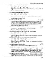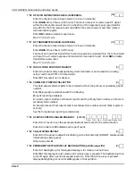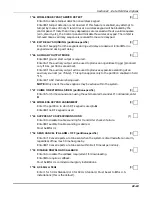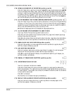
Section 22 – Data Field Descriptions
22-11
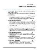
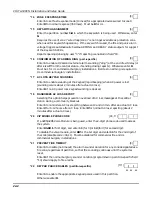
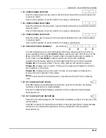
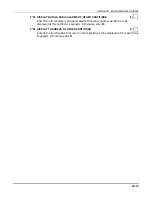
1*23 CROSS ZONING PAIR TWO
|
|
Enter the second pair of zones, which must both be faulted within a five-minute period
to cause an alarm.
Enter 00,00 to disable. Must be 00,00 for UL burglary installations.
1*24 CROSS ZONING PAIR THREE
|
|
Enter the third pair of zones, which must both be faulted within a five-minute period to
cause an alarm.
Enter 00,00 to disable. Must be 00,00 for UL burglary installations.
1*25 CROSS ZONING PAIR FOUR
|
|
Enter the fourth pair of zones, which must both be faulted within a five-minute period
to cause an alarm.
Enter 00,00 to disable. Must be 00,00 for UL burglary installations.
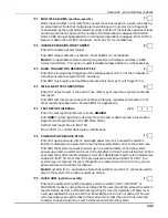
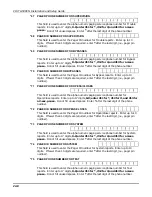
1*26 PANIC BUTTON OR SPEEDKEY [00,00,00,00]
|
|
|
|
A
B
C
D
For each lettered key A-C, enter 00 to assign that key’s respective panic function, or
enter a speedkey macro number 01-32 to assign a particular macro to that key. For the
D key, enter 00 to use the D key to select a macro to execute when key is pressed, or
enter a macro number 01-32 to execute a particular macro with the D key.
Instead of the 32 macros, each key can be programmed for any of 3 other functions.
Choice 33 = fire sounder silence. The key, when pressed, will silence fire alarms.
Choice 34 = display next fire alarm. The key, when pressed, will display the next fire
alarm present in the system.
Choice 35 = display previous fire alarm. The key, when pressed, will display the
previous fire alarm present in the system.
Note: Choices 34 and 35 should be used in conjunction with field 1*10 Fire Display
Lock.
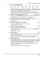
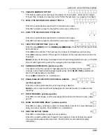
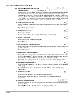
1*28 RF TX LOW BATTERY SOUND
[0]
Enter 0 if display and audible beep annunciation upon RF transmitter low battery
condition is desired only in disarmed state.
Enter 1 if audible beep and display is desired in both armed and disarmed states.
Must be 1 for UL.
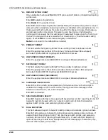
1*29 RF TX LOW BATTERY REPORTING
[0]
Enter 1 if a Trouble message for RF transmitter low battery condition is to be sent to the
central station.
Enter 0 if no report for transmitter low battery is desired. Note that a Trouble message
will be sent for a transmitter supervision failure, independent of this selection.
Must be 1 for UL.
Summary of Contents for VISTA-50PEN
Page 2: ...ii...
Page 10: ...VISTA 50PEN Installation and Setup Guide x...
Page 26: ...VISTA 50PEN Installation and Setup Guide 3 4...
Page 42: ...VISTA 50PEN Installation and Setup Guide 6 6...
Page 56: ...VISTA 50PEN Installation and Setup Guide 8 8...
Page 82: ...VISTA 50PEN Installation and Setup Guide 13 4...
Page 110: ...VISTA 50PEN Installation and Setup Guide 18 8...
Page 118: ...VISTA 50PEN Installation and Setup Guide 20 4...
Page 138: ...VISTA 50PEN Installation and Setup Guide 22 18...
Page 166: ...VISTA 50PEN Installation and Setup Guide 25 6...
Page 172: ...VISTA 50PEN Installation and Setup Guide 27 2...
Page 186: ...VISTA 50PEN Installation and Setup Guide 29 8...
Page 192: ...VISTA 50PEN Installation and Setup Guide 30 6...
Page 197: ...B 1 A P P E N D I X B DIP Switch Tables...
Page 200: ...VISTA 50PEN Installation and Setup Guide B 4...
Page 214: ...l K3271 1BX 9 00 165 Eileen Way Syosset NY 11791 Copyright 2000 PITTWAY Corporation...

