Section 30 – Testing The System
30-3
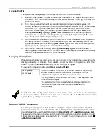
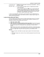
All partitions containing wireless transmitters must be placed in the test mode for sensitivity
reduction of the RF receiver (50% sensitivity). Otherwise, the RF receiver remains at full strength.
•
For multi-partition systems, make sure all partitions are disarmed before entering this mode.
•
Do not conduct this test with your hand wrapped around the transmitter, as this will cause
inaccurate results.
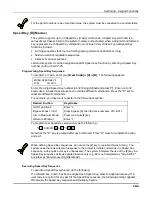
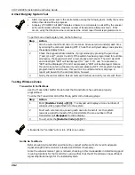
To enter the Go/NoGo Test, perform the following steps:
Step
Action
1
Enter [Installer Code] + [5] TEST.
2
Once transmitters are placed in their desired locations and the approximate
length of wire to be run to sensors is connected to the transmitter's screw
terminals, fault each transmitter.
•
If a single receiver is used, the keypad will beep three times to indicate signal
reception. If two receivers are used, the keypad will beep once if the first
receiver received the signal, twice if the second receiver received the signal,
and three times if both receivers heard the signal (which is desirable for
redundant configurations).
•
If the keypad does not beep, reorient or move the transmitter to another
location. Usually a few inches in either direction is all that is required.
3
Mount the transmitter according to the instructions provided with the
transmitter.
4
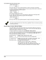
Exit the mode by entering [Installer Code] + [1] OFF.
Trouble Conditions
Supervisory Messages
•
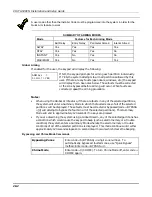
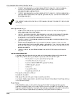
A display of “SUPV” accompanied by a zone number (001-128) and an alpha descriptor (if
programmed) indicates that a fire supervisory condition exists on that zone. This means
that the operation of the fire alarm system may be compromised.
Check or Trouble Messages
•
A display of "CHECK" or "TRBL" (as per field 1*07) accompanied by a zone number (001-
128) and an alpha descriptor indicates that a problem exists with that zone. Zone trouble
may be caused by one of the following conditions:
A hardwired fire zone is open (broken wire)
A Day/Night zone (zone type 5) is faulted
A polling loop zone is not seen by the control panel
A polling loop zone has been tampered (cover removed on a 4190)
A wireless zone has not checked in during the time programmed in field 1*31
A 5800 Series transmitter has been tampered (cover removed)
•
"CHECK" accompanied by a numeric display of "6XX," where XX = 01-32, indicates a
trouble on a 4204CF Supervised Bell Output (corresponding relay number 01-32).
Summary of Contents for VISTA-50PEN
Page 2: ...ii...
Page 10: ...VISTA 50PEN Installation and Setup Guide x...
Page 26: ...VISTA 50PEN Installation and Setup Guide 3 4...
Page 42: ...VISTA 50PEN Installation and Setup Guide 6 6...
Page 56: ...VISTA 50PEN Installation and Setup Guide 8 8...
Page 82: ...VISTA 50PEN Installation and Setup Guide 13 4...
Page 110: ...VISTA 50PEN Installation and Setup Guide 18 8...
Page 118: ...VISTA 50PEN Installation and Setup Guide 20 4...
Page 138: ...VISTA 50PEN Installation and Setup Guide 22 18...
Page 166: ...VISTA 50PEN Installation and Setup Guide 25 6...
Page 172: ...VISTA 50PEN Installation and Setup Guide 27 2...
Page 186: ...VISTA 50PEN Installation and Setup Guide 29 8...
Page 192: ...VISTA 50PEN Installation and Setup Guide 30 6...
Page 197: ...B 1 A P P E N D I X B DIP Switch Tables...
Page 200: ...VISTA 50PEN Installation and Setup Guide B 4...
Page 214: ...l K3271 1BX 9 00 165 Eileen Way Syosset NY 11791 Copyright 2000 PITTWAY Corporation...

