VISTA-50PEN Installation and Setup Guide
4-2
UL
To provide certificated burglary service for UL installations, refer to the special requirements and
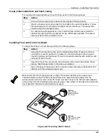
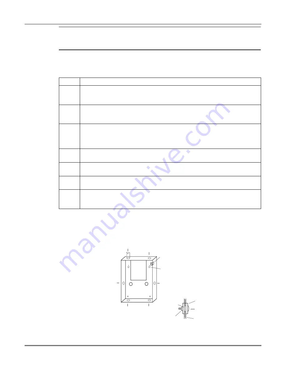
Figure 4-2 Cabinet Attack Resistance Considerations
to follow.
Grade A Mercantile Premises Listing
For a Grade A Mercantile Premises listing, perform the following steps:
Step
Action
1
The panel door must be supervised. Mount the clip-on tamper switch
(supplied) to the cabinet's right side wall as shown in figure 4-2. Wire it to one of
the hardwire zones.
2
Use a bell with a tamper-protected housing such as the ADEMCO AB12.
The bell housing's tamper switch and inner tamper linings must also be wired to
the hardwire zone.
3
Assign the hardwire zone to a burglary partition. Program the hardwire
zone for day trouble/night alarm (zone type 5) when only one burglary partition
is used. Program it for 24-hr. audible alarm (zone type 7) when more than one
burglary partition is used.
4
All wiring between the bell and panel must be run in conduit. Remaining
wires do not need to be run in conduit.
5
All wiring which is not run in conduit must exit from the knockout
openings on the bottom or back of the cabinet.
6
All unused knockouts must be plugged using the disc plugs and carriage
bolts (supplied), as indicated in figure 4-2.
7
Fasten the cabinet door to the cabinet backbox using the 18 one-inch-long
Philips-head screws (supplied) after all wiring, programming and checkout
procedures have been completed.
CABINET ATTACK RESISTANCE CONSIDERATIONS
(Shows typical local Grade A listing installation)
C-COM
PCB
1
1
RUN BELL WIRES
IN CONDUIT
▲
▲
PLUG THIS
KNOCK-OUT
▲
CLIP-ON DOOR
TAMPER SWITCH
CABINET
MOUNTING HOLE
(4 PLACES)
▲
PLUG THIS
KNOCK-OUT
PLUG THIS
KNOCK-OUT
PLUG THIS
KNOCK-OUT
▲
▲
▲
RUN ALL REMAINING
WIRES THRU HERE
▲
TO PLUG AN UNUSED KNOCKOUT OPENING, REMOVE KNOCKOUT AND
INSTALL A PAIR OF DISC PLUGS AND A CARRIAGE BOLT AS SHOWN:
KNOCK-OUT
OPENING
DISC PLUGS (DIMPLES IN DISC
PLUG SHOULD REGISTER INSIDE
KNOCK-OUT OPENING
CARRIAGE BOLT
HEX NUT AND
LOCK WASHER
CABINET SIDEWALL
(OUTSIDE)
▲
▲
▲
▲
▲
Figure 4-2: Cabinet Attack Resistance Considerations
Summary of Contents for VISTA-50PEN
Page 2: ...ii...
Page 10: ...VISTA 50PEN Installation and Setup Guide x...
Page 26: ...VISTA 50PEN Installation and Setup Guide 3 4...
Page 42: ...VISTA 50PEN Installation and Setup Guide 6 6...
Page 56: ...VISTA 50PEN Installation and Setup Guide 8 8...
Page 82: ...VISTA 50PEN Installation and Setup Guide 13 4...
Page 110: ...VISTA 50PEN Installation and Setup Guide 18 8...
Page 118: ...VISTA 50PEN Installation and Setup Guide 20 4...
Page 138: ...VISTA 50PEN Installation and Setup Guide 22 18...
Page 166: ...VISTA 50PEN Installation and Setup Guide 25 6...
Page 172: ...VISTA 50PEN Installation and Setup Guide 27 2...
Page 186: ...VISTA 50PEN Installation and Setup Guide 29 8...
Page 192: ...VISTA 50PEN Installation and Setup Guide 30 6...
Page 197: ...B 1 A P P E N D I X B DIP Switch Tables...
Page 200: ...VISTA 50PEN Installation and Setup Guide B 4...
Page 214: ...l K3271 1BX 9 00 165 Eileen Way Syosset NY 11791 Copyright 2000 PITTWAY Corporation...

