Section 6 – Basic Hardwired Zones
6-3
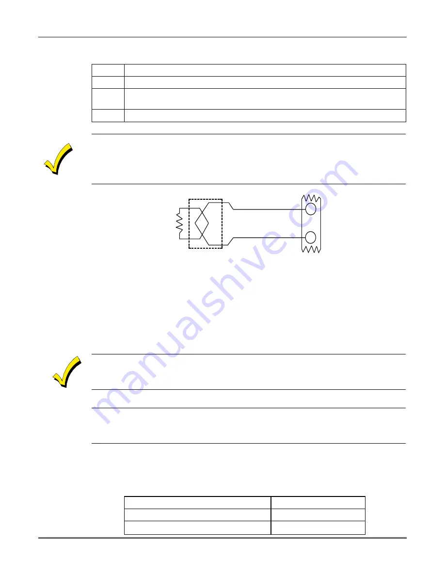
Wiring 2-wire Smoke Detectors
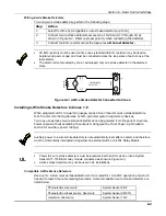
To wire 2-wire smoke detectors, perform the following steps:
Step
Action
1
Select from the list compatible 2-wire smoke detectors (up to 16).
2
Connect 2-wire smoke detectors across zone 1 terminals (10 through 11) as
shown in Figure 6-2. Observe proper polarity when connecting the detectors.
3
Connect the EOL resistor across the loop wires at the last detector.
•
2K EOL resistors must be used on fire zones (standard 2K EOL resistors may be used on
burglary and panic zones) and must be connected across the loop wires of each zone at the
last detector.
•
The alarm current provided by zone 1 will support only one smoke detector in the alarmed
state.
2k EOLR
ZONE 1
SMOKE
(+)
(-)
2-WIRE SMOKE
DETECTOR
10
11
(+)
(-)
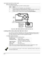
Figure 6-2: 2-Wire Smoke Detector Connected to Zone 1.
Installing 4-Wire Smoke Detectors to Zones 1-8
When programmed for fire warning usage, zones 1-8 can monitor 4-wire smoke detectors,
N.O. fire alarm initiating devices, or N.O. sprinkler system supervisory devices.
You may use as many 4-wire smoke detectors as can be powered from the panel's Auxiliary
Power output without exceeding the output's rating (see the Final Power-Up Procedure
section for auxiliary power ratings).
Auxiliary power to 4-wire smoke detectors is not automatically reset after an alarm, and therefore
must be momentarily interrupted using either an external switch or a 4204 Relay Module.
UL
•
Power to 4-wire smoke detectors must be supervised with an EOL device (use a System
Sensor A77-716B EOL relay module connected as shown in
Figure 6-3
).
•
2-wire smoke detectors may not be used in UL installations.
Compatible 4-Wire Smoke Detectors
Use any UL Listed 4-wire smoke detector which is rated for 10-14VDC operation and which
has alarm reset time not exceeding 6 seconds. Some compatible 4-wire smoke detectors are
listed below.
Photoelectric, direct wire
System Sensor 2412
Photoelectric w/heat sensor, direct wire
System Sensor 2412TH
Ionization, direct wire
System Sensor 1412
Summary of Contents for VISTA-50PEN
Page 2: ...ii...
Page 10: ...VISTA 50PEN Installation and Setup Guide x...
Page 26: ...VISTA 50PEN Installation and Setup Guide 3 4...
Page 42: ...VISTA 50PEN Installation and Setup Guide 6 6...
Page 56: ...VISTA 50PEN Installation and Setup Guide 8 8...
Page 82: ...VISTA 50PEN Installation and Setup Guide 13 4...
Page 110: ...VISTA 50PEN Installation and Setup Guide 18 8...
Page 118: ...VISTA 50PEN Installation and Setup Guide 20 4...
Page 138: ...VISTA 50PEN Installation and Setup Guide 22 18...
Page 166: ...VISTA 50PEN Installation and Setup Guide 25 6...
Page 172: ...VISTA 50PEN Installation and Setup Guide 27 2...
Page 186: ...VISTA 50PEN Installation and Setup Guide 29 8...
Page 192: ...VISTA 50PEN Installation and Setup Guide 30 6...
Page 197: ...B 1 A P P E N D I X B DIP Switch Tables...
Page 200: ...VISTA 50PEN Installation and Setup Guide B 4...
Page 214: ...l K3271 1BX 9 00 165 Eileen Way Syosset NY 11791 Copyright 2000 PITTWAY Corporation...

