VISTA-50PEN Installation and Setup Guide
7-4
Wiring Polling Loop Devices
When running polling loop wires, they must not be run within 6" of AC power, telephone, or
intercom wiring. Since the polling loop is carrying data between the control panel and the
devices, interference on this loop can cause an interruption of this communication. The polling
loop can also cause outgoing interference on the intercom or phone lines. If this spacing cannot
be achieved, shielded wire must be used. (Note that the maximum total wire length supported is
cut in half when shielded wire is used.)
To wire the polling loop devices, perform the following steps:
Step
Action
Select from the list compatible polling loop devices.
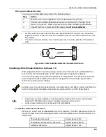
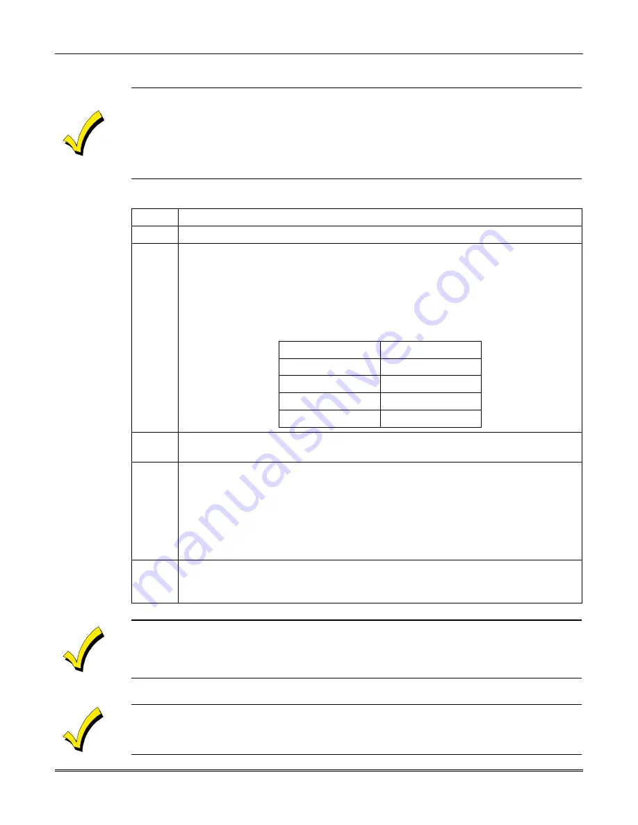
Run wires to each device on the polling loop. No individual wire run may exceed
the lengths given in the table to follow. In addition, no more than 64mA may be
drawn on any individual wire run. When a star configuration is used, the total
length of all wire runs combined cannot exceed 4000 ft (2000 ft. if using
unshielded wire in conduit or shielded wire). Twisted-pair is recommended for
all normal wire runs.
Maximum Polling Loop Wire Runs
Wire Gauge
Max. Length
#22 gauge
650 feet
#20 gauge
950 feet
#18 gauge
1500 feet
#16 gauge
2400 feet
2
3
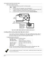
Wire each device to the polling loop, making sure to use correct polarity when
making connections (refer to the device's instructions).
4
If you are using serial number devices, and intend to have the control enroll
each serial number automatically, wire no more than 25 of these devices to the
control at a time. Then power up and program them before connecting the next
25. Leave previously enrolled devices connected.
Note: If you intend to manually enter the serial numbers through the keypad or
through Compass downloading software, all the devices may be connected before
powering up to program.
5
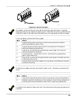
If you are using devices with DIP switches, set each device's DIP switches
for the zone number you are assigning it. Refer to the device's instructions or the
DIP Switch Tables at the end of this manual when setting addresses.
Certain polling loop devices have a DIP switch which can be used either to select the device's
zone number or to select the enrolling of a unique, embedded serial number by the control panel.
When used with VISTA-50PEN, these devices MUST be set for the serial number mode of
operation.
Be sure to include the total current drawn on the polling loop when figuring the total auxiliary load
on the panel's power supply (use the AUXILIARY CURRENT DRAW WORKSHEET in the
Final
Power Up Procedure
section.
Summary of Contents for VISTA-50PEN
Page 2: ...ii...
Page 10: ...VISTA 50PEN Installation and Setup Guide x...
Page 26: ...VISTA 50PEN Installation and Setup Guide 3 4...
Page 42: ...VISTA 50PEN Installation and Setup Guide 6 6...
Page 56: ...VISTA 50PEN Installation and Setup Guide 8 8...
Page 82: ...VISTA 50PEN Installation and Setup Guide 13 4...
Page 110: ...VISTA 50PEN Installation and Setup Guide 18 8...
Page 118: ...VISTA 50PEN Installation and Setup Guide 20 4...
Page 138: ...VISTA 50PEN Installation and Setup Guide 22 18...
Page 166: ...VISTA 50PEN Installation and Setup Guide 25 6...
Page 172: ...VISTA 50PEN Installation and Setup Guide 27 2...
Page 186: ...VISTA 50PEN Installation and Setup Guide 29 8...
Page 192: ...VISTA 50PEN Installation and Setup Guide 30 6...
Page 197: ...B 1 A P P E N D I X B DIP Switch Tables...
Page 200: ...VISTA 50PEN Installation and Setup Guide B 4...
Page 214: ...l K3271 1BX 9 00 165 Eileen Way Syosset NY 11791 Copyright 2000 PITTWAY Corporation...


