Section 8 – Wireless Zone Expansion
8-3
Installation and Setup of the 5881 RF Receivers
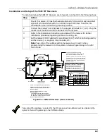
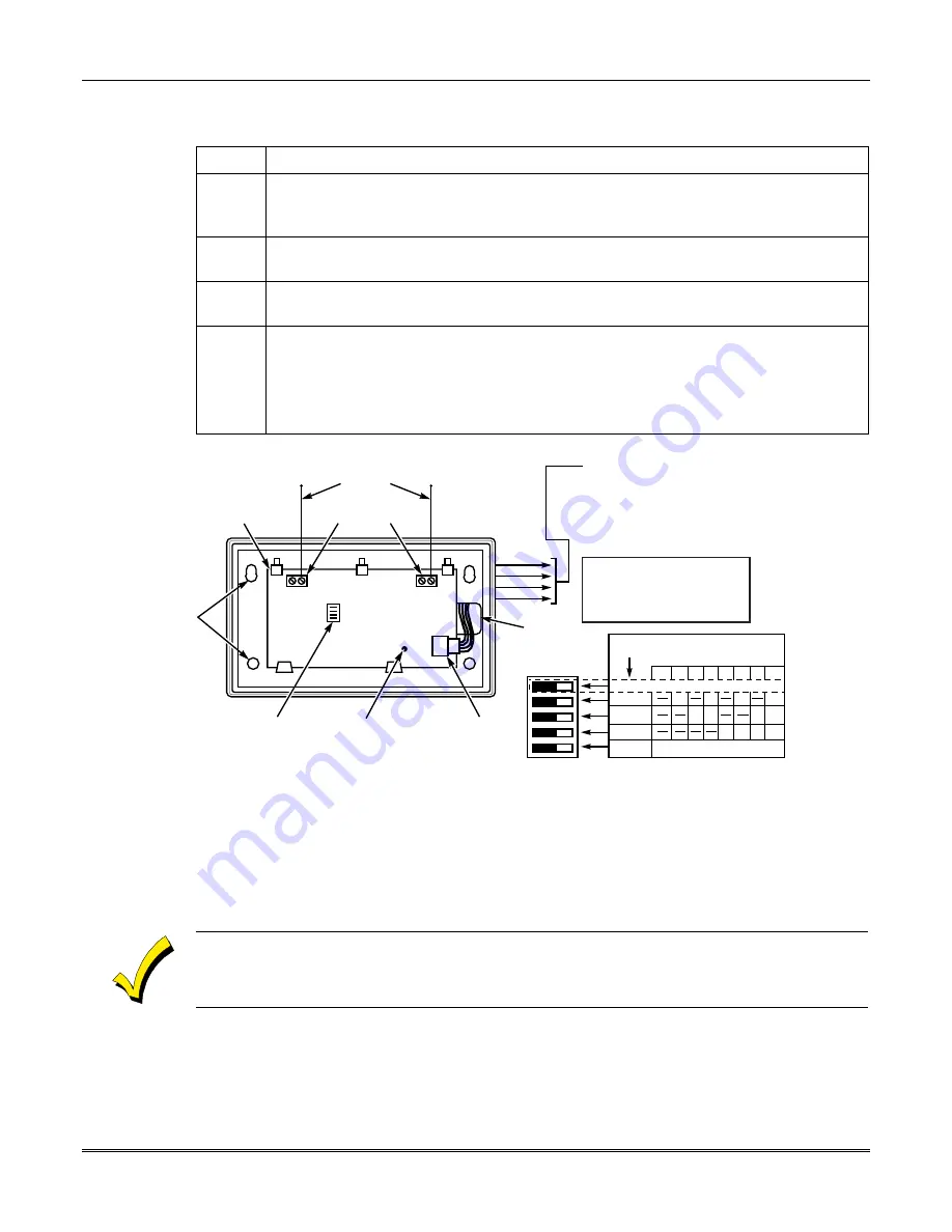
To install and setup the 5881 RF Receiver, see to figure 8-1 and perform the following steps:
Step
Action
Mount the receiver. It must be mounted externally to the control and can detect
signals from transmitters within a nominal range of 200 feet. Take this into
consideration when determining mounting location.
2
Connect the receiver’s wire harness to the keypad terminals (6, 7, 8, 9). Plug the
connector at the other end of the harness into the receiver.
3
Refer to the Installation Instructions provided with the receiver for further
installation procedures regarding antenna mounting, etc.
4
Set the receiver’s DIP switches for an address (01-07) which is not being used by
another device (i.e., keypads, relay modules, etc.).
Note: Take note of this address setting, because you will need it when
programming the receiver into the system in Device Programming in the #93
Menu Mode.
MOUNTING
HOLES
INTERFERENCE
INDICATOR LED
DIP SWITCH
INSERT IN
RIGHT-HAND
TERMINALS
ANTENNAS
YELLOW
RED
BLACK
GREEN
WIRING
OPENING
TO CONTROL'S REMOTE KEYPAD
CONNECTION POINTS. EACH RECEIVER
MUST BE ON INDIVIDUAL HOME RUN.
USE MAX. OF 220 ft. (67m0 OF #22 (0.64mm)
WIRE OR 550 ft. (168m) OF #18 (1mm) WIRE
FOR EACH RUN. 20 ft. MAX. IN COMMERCIAL
FORE INSTALLATIONS. (SEE RECEIVER'S
INSTRUCTIONS.)
PLUG & SOCKET
CIRCUIT
BOARD
DIP SWITCH WHIRE AREAS = SWITCH
HANDLES. POSITION 2-4 DETERMINE
RECEIVER'S ADDRESS. CONSULT
CONTROL'S INSTRUCTIONS FOR
ADDRESS TO USE. DIP SWITCH BELOW
SHOWN SET FOR ADDRESS "0."
SWITCH
POSITION
RECEIVER ADDRESS SETTINGS
(" - " MEANS OFF)
0 1 2 3 4 5 6 7
4
3
2
1
5
PRESENT ONLY ON 5881EH (SEE TEXT AT LEFT)
ON
ON
ON
ON
ON
ON
ON
ON
ON
ON
ON
ON
FOR FUTURE USE
DIP SWITCH #5 (PRESET ONLY ON 5881EH)
ON: SETS 5881EH FOR USE IN COMMERCIAL
FIRE APPLICATIONS (SEE THE RECEIVER'S
INSTRUCTIONS)*.
OFF: USE IN NON-COMMERCIAL FIRE
INSTALLATIONS.
* FOR COMMERCIAL FIRE APPLICATIONS
THE 5881EH PC BOARD MUST BE MOUNTED
IN A SEPARATE CABINET (SEE RECEIVER'S
INSTRUCTIONS FOR DETAILS).
Figure 8-1. 5881 RF Receiver (cover removed)
Take note of the address you select for the RF receiver as this address must be enabled in the
system’s
Device Programming
in the
#93 Menu Mode
.
Summary of Contents for VISTA-50PEN
Page 2: ...ii...
Page 10: ...VISTA 50PEN Installation and Setup Guide x...
Page 26: ...VISTA 50PEN Installation and Setup Guide 3 4...
Page 42: ...VISTA 50PEN Installation and Setup Guide 6 6...
Page 56: ...VISTA 50PEN Installation and Setup Guide 8 8...
Page 82: ...VISTA 50PEN Installation and Setup Guide 13 4...
Page 110: ...VISTA 50PEN Installation and Setup Guide 18 8...
Page 118: ...VISTA 50PEN Installation and Setup Guide 20 4...
Page 138: ...VISTA 50PEN Installation and Setup Guide 22 18...
Page 166: ...VISTA 50PEN Installation and Setup Guide 25 6...
Page 172: ...VISTA 50PEN Installation and Setup Guide 27 2...
Page 186: ...VISTA 50PEN Installation and Setup Guide 29 8...
Page 192: ...VISTA 50PEN Installation and Setup Guide 30 6...
Page 197: ...B 1 A P P E N D I X B DIP Switch Tables...
Page 200: ...VISTA 50PEN Installation and Setup Guide B 4...
Page 214: ...l K3271 1BX 9 00 165 Eileen Way Syosset NY 11791 Copyright 2000 PITTWAY Corporation...


