VISTA-50PEN Installation and Setup Guide
10-4
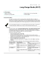
If Touch-tones are not present following phone access to the security system via an on-
premises phone, try reversing the pair of wires connected to terminals 3 and 4 on the
4285/4286.
If the phone plug is disconnected from the control, the premise’s phones will not operate.
Installing TeleSmart
Mounting the Module
The TeleSmart Module should be mounted in the security system’s control cabinet if space is
available, or within a grounded metal enclosure to provide proper ESD protection.
Mounting Inside the Control’s Cabinet:
Use double-sided tape to attach the module to
the interior surface of the cabinet, or hang it on two screws. Do not mount it on the cabinet
door or attach it to the control’s PC board.
Mounting Outside the Cabinet:
Use the screw holes at the rear of the module. Wires
can be brought out from the side or back (use the round breakout on the back).
Affix the supplied Summary of Connections label to the module’s inside cover or to the inside
of the cabinet door.
Wiring Connections
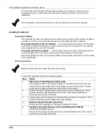
Before making connections, power down the control panel.
To wire the TeleSmart, perform the following steps:
Step
Action
1
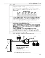
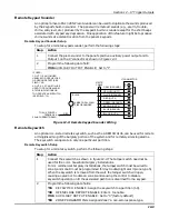
Phone Line Connections (see figure 10-2):
Use a standard RJ31X phone jack (CA38A in Canada) and direct-connect cord.
Connect the direct-connect cord’s red and green wires to the control’s incoming
phone line terminals as described in the control’s instructions.
2
Connect the direct-connect cord’s brown and grey wires to TeleSmart’s “Home
Phones” terminals, disconnecting them from the control’s premises phone
terminals, if previously connected.
3
Connect the control’s local phone TIP and RING terminals to TeleSmart’s “From
Control” terminals, using jumper wires (not supplied).
4
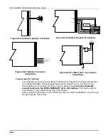
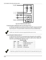
Speaker Connections (see figure 10-3):
Connect an 8 Ohm speaker to TeleSmart’s speaker terminals.
5
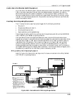
Keypad Connections (see figure 10-4) and Setting the Address:
Use 6162 addressable keypads.
Disconnect those keypads intended to be used with TeleSmart from the control’s
terminals, if previously connected.
Summary of Contents for VISTA-50PEN
Page 2: ...ii...
Page 10: ...VISTA 50PEN Installation and Setup Guide x...
Page 26: ...VISTA 50PEN Installation and Setup Guide 3 4...
Page 42: ...VISTA 50PEN Installation and Setup Guide 6 6...
Page 56: ...VISTA 50PEN Installation and Setup Guide 8 8...
Page 82: ...VISTA 50PEN Installation and Setup Guide 13 4...
Page 110: ...VISTA 50PEN Installation and Setup Guide 18 8...
Page 118: ...VISTA 50PEN Installation and Setup Guide 20 4...
Page 138: ...VISTA 50PEN Installation and Setup Guide 22 18...
Page 166: ...VISTA 50PEN Installation and Setup Guide 25 6...
Page 172: ...VISTA 50PEN Installation and Setup Guide 27 2...
Page 186: ...VISTA 50PEN Installation and Setup Guide 29 8...
Page 192: ...VISTA 50PEN Installation and Setup Guide 30 6...
Page 197: ...B 1 A P P E N D I X B DIP Switch Tables...
Page 200: ...VISTA 50PEN Installation and Setup Guide B 4...
Page 214: ...l K3271 1BX 9 00 165 Eileen Way Syosset NY 11791 Copyright 2000 PITTWAY Corporation...


