VISTA-50PEN Installation and Setup Guide
11-2
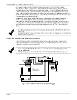
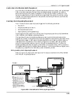
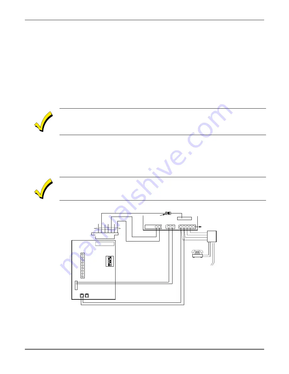
One way to trigger the AAV Module is by selecting option 3 in field 1*46 and make
connections as shown in Figure 11-1. Field 1*46 can be used to set ground start, remote
console sounding, long range radio, or open/close trigger. If any one of these functions are
absolutely necessary in a given installation, the alternative AAV trigger method is via the
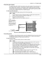
use of a 4204 Relay Module as shown in Figure 11-2. If this method is selected, program the
start and stop conditions for that relay as choice 60 "Audio Alarm Verification" during Output
Programming in the #93 Menu Mode.
Some AAV Modules allow remote triggering by ring detection at the alarm installation.
Please be advised that if this option is selected, it may defeat modem download and
4285/4286 VIP Module remote access capability. The DIP switch settings shown in Figure
11-1, Figure 11-2, and Figure 11-3 disable remote AAV Module trigger option. The control
requires the AAV Module trigger-type as falling edge, which is set in DIP switch settings
shown.
•
685 Receiver software must be rev. 4.6 or higher. Earlier versions will not hold the phone line
connection.
•
Contact ID code for “Listen-in-to-Follow” is 606. Contact ID is the only reporting format that will
send a "Listen-in-to-Follow."
Audio Alarm Verification Module Connections
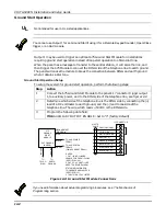
Connect the Audio Alarm Verification Module's falling edge trigger input (terminal 5 on
Eagle model 1250) to J7 connector trigger output, or to a 4204 relay module, as shown in
Figure 11-1, Figure 11-2, and Figure 11-3.
•
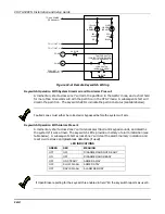
If also using a 4285/4286 VIP Module, be sure to follow the corresponding diagram when
making connections.
•
If the phone plug is disconnected from the control, the premise’s phones will not operate.
CONTROL/
DIALER HEADER
NOTE:
REFER TO AAV MODULE
INSTRUCTIONS FOR
CONNECTIONS TO AUDIO
SPEAKERS AND MICROPHONE.
•
•
•
•
•
EAGLE
1250
6
7
16
17
27
26
28 29 30
}
ZONE 5
(–)
(+)
(–)
(+)
•
•
•
•
•
•
•
•
J7
DIP Switch
1 2 3 4 5 6
ON
CONTROL
EARTH
GROUND
RED (R)
GREEN (T)
GREY (R)
BROWN (T)
INCOMING
PHONE LINE
RJ31X
(–) EDGE TRIGGER (YELLOW)
PIN 3
SYSTEM POWER (RED)
SYSTEM GROUND (BROWN)
BROWN (–)
RED (+)
TIP
RING
EAGLE
SUPPLIED
CABLE
➤ ➤
DIODE FROM
EOLR PACKAGE
TO PREMISES
HANDSET
Figure 11-1: AAV Connections Using the J7 Trigger
Summary of Contents for VISTA-50PEN
Page 2: ...ii...
Page 10: ...VISTA 50PEN Installation and Setup Guide x...
Page 26: ...VISTA 50PEN Installation and Setup Guide 3 4...
Page 42: ...VISTA 50PEN Installation and Setup Guide 6 6...
Page 56: ...VISTA 50PEN Installation and Setup Guide 8 8...
Page 82: ...VISTA 50PEN Installation and Setup Guide 13 4...
Page 110: ...VISTA 50PEN Installation and Setup Guide 18 8...
Page 118: ...VISTA 50PEN Installation and Setup Guide 20 4...
Page 138: ...VISTA 50PEN Installation and Setup Guide 22 18...
Page 166: ...VISTA 50PEN Installation and Setup Guide 25 6...
Page 172: ...VISTA 50PEN Installation and Setup Guide 27 2...
Page 186: ...VISTA 50PEN Installation and Setup Guide 29 8...
Page 192: ...VISTA 50PEN Installation and Setup Guide 30 6...
Page 197: ...B 1 A P P E N D I X B DIP Switch Tables...
Page 200: ...VISTA 50PEN Installation and Setup Guide B 4...
Page 214: ...l K3271 1BX 9 00 165 Eileen Way Syosset NY 11791 Copyright 2000 PITTWAY Corporation...


