12-1
S E C T I O N 1 2
J7 Trigger Outputs
• • • • • • • • • • • • • • • • • • • • • • • • • • • • • • • • • • • • • • • • • • • • • • • • •
In This Section
♦
General Information
♦
Ground Start Operation
♦
Remote Keypad Sounder
♦
Remote Keyswitch
♦
Audio Alarm Verification (AAV) Equipment
♦
Auxiliary Alarm Signaling Equipment
♦
Event Log Printer
• • • • • • • • • • • • • • • • • • • • • • • • • • • • • • • • • • • • • • • • • • • • • • • • •
General Information
The J7 connector, located in the upper right-hand corner of the main PCB, provides 1 input
and seven trigger outputs that can be used to interface to the following:
•
Ground start module
•
Remote keypad sounder
•
UL Listed keyswitch
•
Audio alarm verification device (two-way voice)
•
Auxiliary alarm signaling equipment such as an ADEMCO Long Range Subscriber Radio
•
Event logging serial printer (via the 4100SM Interface Module)
•
PC computer used to direct-wire download the panel's programming information (via the
4100SM Interface Module)
The trigger output ratings are listed below. Note that all outputs are power-limited.
Output 1:
LOW:
2K to ground
HIGH: 10-14 VDC @ 20 mA max
Remaining Outputs:
LOW:
1K to ground
HIGH: 10-14 VDC through 5K
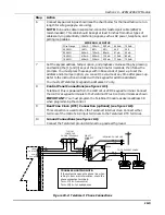
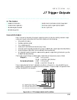
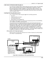
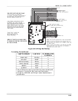
The pin assignments for the J7 connector are shown in Figure 12-1. Use a 4142TR 9-wire
trigger cable (1 supplied) to interface with this connector. The panel does not supervise field
wiring connected to this connector.
1
2
3
4
5
6
7
8
9
4142TR CABLE
GRA
Y (GR
OUND)
YELLO
W (OUT 1)
RED (OUT 2)
GREEN (GR
OUND)
BR
O
WN (OUT 3)
BLUE (GR
OUND)
BLA
CK (OUT 4)
WHITE (GR
OUND)
J7 CONNECTOR
N/U
OUT 1: GROUND START OR OPEN / CLOSE
OUT 2: FIRE OR KEYSWITCH ARMED LED
OUT 3: BURGULARY/AUDIBLE PANIC/AUXILLIARY
OUT 4: SILENT PANIC/DURESS OR KEYSWITCH READY LED
Figure 12-1. J7 Pin Assignments and Functions
Summary of Contents for VISTA-50PEN
Page 2: ...ii...
Page 10: ...VISTA 50PEN Installation and Setup Guide x...
Page 26: ...VISTA 50PEN Installation and Setup Guide 3 4...
Page 42: ...VISTA 50PEN Installation and Setup Guide 6 6...
Page 56: ...VISTA 50PEN Installation and Setup Guide 8 8...
Page 82: ...VISTA 50PEN Installation and Setup Guide 13 4...
Page 110: ...VISTA 50PEN Installation and Setup Guide 18 8...
Page 118: ...VISTA 50PEN Installation and Setup Guide 20 4...
Page 138: ...VISTA 50PEN Installation and Setup Guide 22 18...
Page 166: ...VISTA 50PEN Installation and Setup Guide 25 6...
Page 172: ...VISTA 50PEN Installation and Setup Guide 27 2...
Page 186: ...VISTA 50PEN Installation and Setup Guide 29 8...
Page 192: ...VISTA 50PEN Installation and Setup Guide 30 6...
Page 197: ...B 1 A P P E N D I X B DIP Switch Tables...
Page 200: ...VISTA 50PEN Installation and Setup Guide B 4...
Page 214: ...l K3271 1BX 9 00 165 Eileen Way Syosset NY 11791 Copyright 2000 PITTWAY Corporation...


