VISTA-50PEN Installation and Setup Guide
12-2
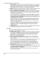
Ground Start Operation
UL
Not intended for use in UL Listed applications..
You cannot use Output 1 for an Ground Start if using it for a Remote Keypad Sounder, Open/Close
trigger, or an AAV module.
Output 1 may be used to trigger an optional 675 Ground Start Module for installations
requiring ground start operation instead of loop start operation to obtain dial tone.
When the panel has a message to transmit to the central station, it will seize the line, and
then trigger the 675 Module to connect the RING side of the telephone line to earth ground.
The panel will cause the module to break the connection between RING and earth ground
when it obtains a dial tone.
Ground Start Operation Setup
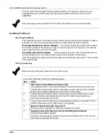
To setup the system for ground start operation, perform the following steps:
Step
Action
1
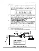
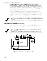
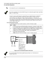
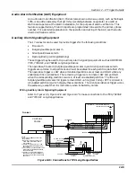
Connect the 675 Ground Start Module to the panel's J7 connector trigger output
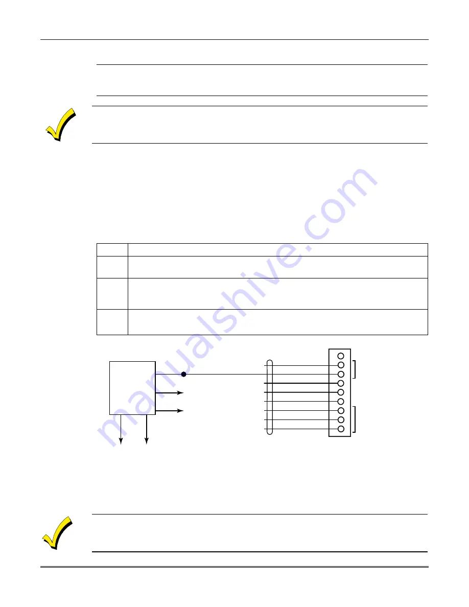
1, to auxiliary power, and to the RING side of the telephone line, see figure 12-2.
2
Determine which side of the telephone line is the RING side by connecting the (+)
lead of a DC voltmeter to earth ground, and the (-) lead to one side of the
telephone line. The wire which reads + 50VDC is the RING side.
3
Program the following data field:
1*46 AUXILIARY OUTPUT ENABLE: Set to "0" (factory default)
12
3456
78
9
4142TR
CABLE
GRAY (GROUND)
YELLOW (OUT 1)
RED (OUT 2)
GREEN (GROUND)
BROWN (OUT 3)
BLUE (GROUND)
BLACK (OUT 4)
WHITE (GROUND)
J7 CONNECTOR
N/U
IF USED:
1. OUT 1 IS NO LONGER
USABLE FOR OPEN / CLOSE
(SEE FIELD 1*46).
2. OUT 2, 3, 4 CAN STILL BE
USED TO PROVIDE ALARM
STATUS INDICATIONS OR
TO OPERATE A KEYSWITCH
(SEE FIELD *15).
3. THE 675 IS NOT UL LISTED.
BR
O
W
N
GROUND START
TRIGGER
BLUE
GREEN
BLACK
VIOLET
TO AUX. POWER
TERM. 7
TO AUX. POWER
TERM. 6
(50mA CURRENT DRAW)
675
GROUND
START
MODULE
(CUT ORANGE
JUMPER)
TO
TELCO
RING
TO
EARTH
GROUND
Figure 12-2: Ground Start Module Connections
If you need information about actual programming procedures, see:
The Mechanics of
Programming
section
.
Summary of Contents for VISTA-50PEN
Page 2: ...ii...
Page 10: ...VISTA 50PEN Installation and Setup Guide x...
Page 26: ...VISTA 50PEN Installation and Setup Guide 3 4...
Page 42: ...VISTA 50PEN Installation and Setup Guide 6 6...
Page 56: ...VISTA 50PEN Installation and Setup Guide 8 8...
Page 82: ...VISTA 50PEN Installation and Setup Guide 13 4...
Page 110: ...VISTA 50PEN Installation and Setup Guide 18 8...
Page 118: ...VISTA 50PEN Installation and Setup Guide 20 4...
Page 138: ...VISTA 50PEN Installation and Setup Guide 22 18...
Page 166: ...VISTA 50PEN Installation and Setup Guide 25 6...
Page 172: ...VISTA 50PEN Installation and Setup Guide 27 2...
Page 186: ...VISTA 50PEN Installation and Setup Guide 29 8...
Page 192: ...VISTA 50PEN Installation and Setup Guide 30 6...
Page 197: ...B 1 A P P E N D I X B DIP Switch Tables...
Page 200: ...VISTA 50PEN Installation and Setup Guide B 4...
Page 214: ...l K3271 1BX 9 00 165 Eileen Way Syosset NY 11791 Copyright 2000 PITTWAY Corporation...


