VISTA-50PEN Installation and Setup Guide
14-2
VistaKey Features
VistaKey features are as follows:
•
Each VistaKey communicates with the VISTA-50PEN via a special global polling protocol
of the V-Plex polling loop.
•
In the event local power to the VistaKey is lost, the VistaKey module provides back-up
monitoring of the Access Point door via a built-in V-Plex device that is powered solely
from the polling loop. It is programmed as a new type of V-Plex device as part of the
control’s V-Plex Device Programming. A serial number label is affixed to the VistaKey
module for manual entry of its serial number.
•
The VistaKey supports up to 250 cardholders.
•
All configurable options for each VistaKey are accomplished via software, firmware, and
non-volatile memory, eliminating the need for PC board jumpers.
•
Access Point zone numbers (1-15) are assigned via a user-friendly, 16-position rotary
switch.
•
The addition and removal of VistaKey modules from the system is easily accomplished
via the VISTA-50PEN keypad.
•
Each VistaKey provides one open-collector output trigger (sink 12mA @ 12VDC).
Mounting and Wiring the VistaKey
To mount and wire the VistaKey module, perform the following steps:
Step
Action
1
Mount the VistaKey, Door Strike or Mag Lock, and Card Reader.
2
If applicable, mount the Door Status Monitor (DSM) and/or Request to Exit (RTE)
devices.
3
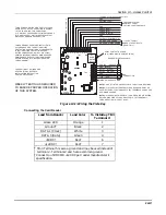
Using Figure 14-1 at the end of this section as a reference, connect the Card
Reader interface cable to TB3, making the +5v or +12v connection last.
4
Connect the leads to TB1 in the following order:
a.
All ground leads to terminals 2, 5 and 9).
b.
The (optional) DSM, RTE, and General Purpose leads to terminals 6, 7, and
8, respectively.
c.
Door Strike (or Mag Lock) lead to terminal 10.
d.
Local +12v or +24v supply lead to terminal 1.
e.
Local +12v or +24v supply lead to the N/C relay terminal 11 (if a Mag Lock is
being used), OR to the N/O relay terminal 10 (if a door strike is being used).
5
Connect the – polling loop and + polling loop leads (from the VISTA-50PEN) to
terminals 4 and 3 respectively.
6
Set the Address Select switch to the desired access door number (1-15).
7
Repeat steps 1 through 6 for each VistaKey being installed.
Summary of Contents for VISTA-50PEN
Page 2: ...ii...
Page 10: ...VISTA 50PEN Installation and Setup Guide x...
Page 26: ...VISTA 50PEN Installation and Setup Guide 3 4...
Page 42: ...VISTA 50PEN Installation and Setup Guide 6 6...
Page 56: ...VISTA 50PEN Installation and Setup Guide 8 8...
Page 82: ...VISTA 50PEN Installation and Setup Guide 13 4...
Page 110: ...VISTA 50PEN Installation and Setup Guide 18 8...
Page 118: ...VISTA 50PEN Installation and Setup Guide 20 4...
Page 138: ...VISTA 50PEN Installation and Setup Guide 22 18...
Page 166: ...VISTA 50PEN Installation and Setup Guide 25 6...
Page 172: ...VISTA 50PEN Installation and Setup Guide 27 2...
Page 186: ...VISTA 50PEN Installation and Setup Guide 29 8...
Page 192: ...VISTA 50PEN Installation and Setup Guide 30 6...
Page 197: ...B 1 A P P E N D I X B DIP Switch Tables...
Page 200: ...VISTA 50PEN Installation and Setup Guide B 4...
Page 214: ...l K3271 1BX 9 00 165 Eileen Way Syosset NY 11791 Copyright 2000 PITTWAY Corporation...

