VISTA-50PEN Installation and Setup Guide
16-2
1
2
3
4
5
6
7
8
9
NU
J8 CONNECTOR
VIOLET
GREY
YELLOW
RED
GREEN
BROWN
BLUE
BLACK
IN 2
GROUND
IN 3
GROUND
OUT 5
OUT 6
GROUND GROUND
PRINTER DTR
4142TR CABLE (SUPPLIED WITH 4100SM)
8
7
6
5
4
3
2
1
4100SM SERIAL MODULE
+ PWR
- (GND)
RXD
not used
not used
TXD
not used
DTR
RED BLUE WHITE
To TB6 Aux. Power (+)
(25mA current draw)
To TB7 Aux. Power (-)
4100SM JUMPERS
(CUT TO SET RESPECTIVE SIGNAL FLOATING)
COLOR
FUNCTION
PIN#
RED
CD
8
BLUE
CTS
5
WHITE
DSR
6
USE GENDER CHANGER
SUPPLIED WITH 4100SM
IF PRINTER HAS DB25
MALE CONNECTOR
3M
Cable
Supplied with
4100SM
SERIAL PRINTER
SET FOR: 8 DATA BITS
EVEN PARITY
STOP BIT
300/1200 BAUD
HARDWARE HANDSHAKE
USING DTR SIGNAL
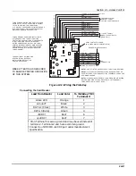
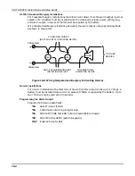
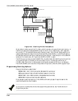
Figure 16-1. Event Log Printer Connections
Most printers either ignore the CTS, DSR, and CD signals, or require them to be high (i.e., 3-
15VDC as measured on RS232 DB25 Connector Pins 5, 6 & 8, respectively, with respect to
Ground Pin 7). The 4100SM Module sets these pins high. If the printer being used will not
operate with these pins high, then clip the blue (CTS), white (DSR), or red (CD) jumpers on
the 4100SM Module to set the corresponding signal floating. Important pins on the RS232C
cable are Pin 3 (data out), Pin 7 (ground) and Pin 20 (DTR - ready).
The DTR signal, as measured at 4100SM TB1, should be high (9.5-14VDC) when the printer
is powered, properly connected, on-line and ready to print. This signal will be low (0-
1.5VDC) when the printer is not powered, not properly connected, off-line or out of paper.
The VISTA-50PEN will not send printing data to the printer unless the DTR signal is high.
Programming Event Log Options
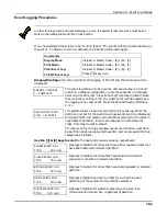
Program the following data fields:
1*70 EVENT LOG TYPES (1=enable; 0=disable for each type)
1*71 12/24 HOUR TIME STAMP FORMAT (0=12 hr; 1=24 hr)
1*72 EVENT LOG PRINTER ON-LINE (0=disable; 1=enable)
1*73 PRINTER BAUD RATE (1=300; 0=1200)
Enter Report Code Programming in the #93 Menu Mode to program report codes for the
event log (System Group #4 codes).
If you need more information about actual programming procedures, see
The Mechanics of
Programming
section
.
Summary of Contents for VISTA-50PEN
Page 2: ...ii...
Page 10: ...VISTA 50PEN Installation and Setup Guide x...
Page 26: ...VISTA 50PEN Installation and Setup Guide 3 4...
Page 42: ...VISTA 50PEN Installation and Setup Guide 6 6...
Page 56: ...VISTA 50PEN Installation and Setup Guide 8 8...
Page 82: ...VISTA 50PEN Installation and Setup Guide 13 4...
Page 110: ...VISTA 50PEN Installation and Setup Guide 18 8...
Page 118: ...VISTA 50PEN Installation and Setup Guide 20 4...
Page 138: ...VISTA 50PEN Installation and Setup Guide 22 18...
Page 166: ...VISTA 50PEN Installation and Setup Guide 25 6...
Page 172: ...VISTA 50PEN Installation and Setup Guide 27 2...
Page 186: ...VISTA 50PEN Installation and Setup Guide 29 8...
Page 192: ...VISTA 50PEN Installation and Setup Guide 30 6...
Page 197: ...B 1 A P P E N D I X B DIP Switch Tables...
Page 200: ...VISTA 50PEN Installation and Setup Guide B 4...
Page 214: ...l K3271 1BX 9 00 165 Eileen Way Syosset NY 11791 Copyright 2000 PITTWAY Corporation...


