background image

Summary of Contents for Vista AT 4140

Page 1: ...g a Custom Message Display Only Usable on 5137 Consoles 57 Testing the System 58 5137 LCD Viewing Angle Adjustment 59 Using the Built in Quick Reference User s Manusl 60 Turning the System Over to the User 60 Recalling Alarm and Trouble Messages 60 Fuses in the 4140 61 Replacement Parts 61 Optional Accessories 62 FCC Statement 63 Specifications 64 4140 Security Control 64 5137 4137 Remote Console ...

Page 2: ...ammed to a set of values that is designed to meet the needs of many installations However these can be altered by the installer to suit the specific needs of a particular installation or installation company following the instructions provided in the programming section of this manual factory programmed values are also shown there This system also contains abbrwiated operating instructions in memo...

Page 3: ...inst compromise by someone attempting to defeat the system using 4 levels of security protection 1 2 3 4 Security Code Handshake An 8 digit Central Station ID code must be matched between the No 4140 and the Central Station Hang up and call back Calling the No 4140 does not directly SI 1OW programming as a successful handshake merely results in the No 4140 breaking the phone line connection and th...

Page 4: ...am Download To Shut Down Caumunication dialer Functions non payment of monitoring fees in an owner s system To Shut Down all Security System Functions non payment for a leased system To Inhibit Local Keypad Programming prevents takeover of your accounts 2 Status Commands To Cause the Systm to the central station To Read System Status Arming Status Upload a Copy of its Resident Program to Ready Sta...

Page 5: ...uch alarm conditions fran the local and expansion zones would not be missed only delayed A copy of the progrsm downloaded may be produced from either the No 699 Intelligent Programmer or the IBM PC compatible computer using those products internal report generators when an optional printer is connected ZONE TYPES AVAILABLE FOR SELECTION For 1 2 3 4 each zone used one of the following zone types mu...

Page 6: ...e for disarming purposes first entering whether inside or Ideal for an area such as an apartment entrance foyer in which the only Console is located FONCl IONALDESCRIPTION OF ZONE TYPES The following is a description of the various zone types available which must be selected for each physical zone You may wish to use Table A at the end of this description to record your selections Type 1 BURGLARY ...

Page 7: ...ne will always have Exit Delay 1 The zone has an Entry Delay if preceded by a fault in an Entry Exit zone type 1 or 2 If not preceded by an Entry Exit zone fault an immediate audible local console and external alarm latched display and a programmed caumunicator report are initiated Depressing any key at the Console will silence the Console sounder for 10 seconds A system wide programmed number of ...

Page 8: ... the Console sounder for 10 seconds Keying the security code plus OFF will permanently silence the alarm A system wide programmed number of alarm reports for this zone will be allowed to be transmitted swinger suppression by the canrnunicator until an OFF sequence is performed The communicator will transmit a restoral message when the zone is restored for a time greater than its physical response ...

Page 9: ...ime greater than its physical response time less than 1 second During the disarmed state a faulted zone will result in a DISARMED Press to show faults display 5137 or aNOT READY display 4137 Subsequent depression of the key will and or numbers of the faulted zones to be communicator reports will be initiated cause all the descriptors sequentially displayed No TABLE A ZONE ASSIGNMENTS A zone type m...

Page 10: ...The instsller programs the Installer Code initially as part of the programming procedure see mprogrming he Security Control In this system the installer is considered to be user 1 The installer code permits re entry into the programming mode unless 98 has been previously used to exit the programming mode and also allows access to the normal functions of the systen During initial programming the in...

Page 11: ...ry codes to users 4 14 if required but in the typical arrangement shown in Application 1 there may never be a practical need for this If so the primary user 2 can elect to omit user 3 when assigning secondary codes In the configuration shown in Application 2 user 3 who is the primary user may need to assign secondary temporary codes to maids cleaning persons etc Since the system allows user 3 to a...

Page 12: ...Arm Disarm the System UnUDUser 6 User 3 can assign secondary codes to users 4 142 1 A seconda temporary code is ZiSSig asfOllOWS OUnDUser 7 User 2 Master Code CODE key User 03 1 5 Temporary Code UUUU ser 8 2 User 3 can assign temporary codes as follows UDUU User 9 User 3 Code CODE key User 04 14 Temporary Code UUODUser 10 UOUu User ll UUUD ser 12 ODUUUser 13 UOUUUser 14 UUUu ser 15 12 ...

Page 13: ...ner etc since user 3 is the primary user of the system in this application A secondary code is assigned as follows Master Code CODE key User 03 1 5 Secondary Code 2 A temporary code is assigned as follows User 3 Code CODE key User 04 1 4 Temporary Code CAN ASSIGN TEMPORARY CODES TO 2 TEMPORARY SECURITY CODES MAID CLEANING PERSON ETC tKK3D User 4 14 Jxlun Clulxl lznnn Cluan nnlxl Uncln Cllxlcl noon...

Page 14: ... be used and the high side of the zone will be found on TB2 4 if programmed for fire usage In this application Terminal 1 would not be used 3 Zone 2 4 Zones 2 and 3 Return 5 Zone 3 6 Zone 4 7 Zones 4 and 5 Return 8 Zone 5 9 Console Data Out YELLOW 10 Console Data In GREEN Zone that is programmable for use as a N C sensor loop or as end of line resistor supervised N O N C sensor loop m Terminals 1 ...

Page 15: ...ust be wired to TB2 6 on Control 3 Siren 4 Siren 5 Not used 6 Not used 7 Trigger must be wired to TB2 8 on Control Digital Communication Interface Board Connections Phone Line Interface Terminals 1 Ground Start Output to BLUE LEAD on No 675 Ground Start Module 2 Incaning Phone Line TIP 3 Incoming Phone Line RING 4 Handset RING 5 Handset TIP Warning To prevent the risk of shock disconnect telephone...

Page 16: ... 1 dOO1 3 N 3 SN0dS3H 1SV3 6 ilNOZ I 1 1 I I ...

Page 17: ...TO TB2 10 I I J SUGGESTED PARTS FoR REMOTE KEYSWITCH I No 9787 lVPE SLIM XN3LE LEO PLATE 1 No 112 N C TM4PER SW77CH I EOLR No 4073 70 HIGN SECURllY KEYIOCK SPRING LOADED IN O I U L USTEO ITEM i N3707 1O 1O PIN MALE TC MAI E AOAPTER LEO lNTERFiCE 6A4131 10 IWPIN CONNECTCR W77N 1 E Lk3 I J proper 7 I I I I I I I I i I I I I I 1 i I 1 Diagram 2 KEYSWITCH WIRING Optional Remote Keypad Connection 4131 ...

Page 18: ...ted to the terminals on the Control as indicated in Table C which shows console wire colors and their assignments The auxiliary current capability of the system can be expanded if desired by not using the Console Power input to power consoles except when AC pwer is absent The latter allows the entire auxiliary current to be used for motion detectors and other auxiliary devices as well as allowing ...

Page 19: ...front of the console must be removed to release the back cover see Diagram 4 for screw location Pass the interface wiring through the opening in the back cover and then mount the back cover to the wall surface with screws Splice the interface wiring to the console wires or to the wires on the interface connector supplied with later production 4137s See Diagram 1 and Table C for wire colors and ass...

Page 20: ...ace connector supplied with later production 4137s See Diagram 1 and Table C for wire colors and assignments Note that the Blue wire on the console may not necessarily be used Insulated solderless wire splices such as Ademco No 311 may be used for splicing Check all wire connections carefully before splicing 4 If a late production 4137 is being used attach the interface connector to the board at t...

Page 21: ...tion DO NOT OVERTIGHTEN 8 Insert the small nameplate supplied into the recessed opening to cover the screw head at the front of the console as prwiously shown in Diagram 4 i I I I I i I I I I I I I I I I I I I I i I I 1 11 II I II II I I k Ill Ill II STUDS Ill 1 1 II 11 Ill II 1 WOTE A ROUGWIN nlNG 14133 MAYBE F ESENT IN NEW CONSTRUCTION IF SO SIMPLY REMOVE COVER PLATE TO EXPOSEFRAMEO S3PENINGSLHT...

Page 22: ... s premises prior to the actual installation Simply apply power temporarily a he control and the program the unit as desired When programming from the console note the following 1 Enter the Programming mode by simultaneously depressil The and keys within 30 seconds after pwer is applied to the Control or subsequently k y keying the code 4 1 4 O followed by depression of CODE O O keys Once an insta...

Page 23: ... to programming mode via Type 3 entry method above unless console programming has been locked out by the remote downloader 8 inhibits re entry to programming mode via Type 3 entry method Note When the programming mode is exited a I minute set up period must elapse before the system can properly function ADVANCE TO FIELD PRCXGRAMFIELD ERASE FIELDS READ FIELD RESTORE FACTORY PROGRAM SETTINGS EITCERZ...

Page 24: ...sten for bench test so that familiarity with the operation of the system can be achieved in a shorter period of time The factory preset values are defined in the Table that follows TABLE D FACYCORYPROGRAMMING Address Function Factory Programmed Value 00 INSTALLER CODE 41 11 41 01 01 MASTER SECURITY CODE 11 21 31 41 02 ASSIGN RESPONSE Z1 01 91 TYPE EOR ZONES Z2 0 31 1 8 Z3 0 41 Z4 0 51 Z5 11 01 Z6 ...

Page 25: ...LOSS SOUNDING NOT USED NOT USED NOT USED DISABLE FIRE TIME OUT FIRE INDICATION ON DISPLAY MULTIPLE ALARMS TAMPER DETECTION DISABLE ZONES 10 17 DURESS REPORT DISABLE ADEMCO HIGH SPEED NOT USED 01 01 01 01 01 01 01 01 Short in Wiring to Zone Expander displays 97 01 01 1 and Panic displays 95 01 01 3 and Panic displays 96 01 01 and Panic displays 99 01 01 01 01 01 01 01 Zones 10 16 none 01 zcm 17 non...

Page 26: ...T PRIMARY ACK WAIT PRIMARY TRANSMISSION FORMAT 2 24 hours 1 YES 1 Enabled 11 Touch Tone No Entry No Entry No Entry No Entry No Entry 11 51 11 51 11 51 11 51 11 51 11 51 11 51 11 51 1 1 Dialer Shutdown enabled 2 1 System Shutdown enabled 3 0 Not Used 4 1 Remote Bypass enabled 5 11 Remote Disarm enabled 6 1 Remote Arm enabled 7 1 Upload Program enabled 8 11 Dcwnload Program enabled 01 01 All non fir...

Page 27: ...EPORT TROUBLE REPORT OPEN CLOSE REPORT LOW BATTERY AC LOSS AND TEST REPORT CHANNEL ASSIGNED TO EACH ZONE CHANNEL ASSIGNED TO EACH ZONE CONT D 01 Radionics with 0 9 B F reporting 0 No 11 01 01 01 01 01 01 01 disabled for Users 2 8 01 Not selected 01 Not selected 01 Standard report 1 Expanded 01 Standard report 01 Standard report 01 Standard report 01 Standard report 1 0 01 Zeroes for zones 1 8 no c...

Page 28: ... TO EACH CHANNEL NT D 67 NON ALARM CODES 68 NON ALARM CODES CONT D 69 ZONE TYPES 1 4 RESTORE REPORT ENABLE 70 ZONE TYPES 5 8 RESTORE REPORT EIWBLE All zeroes in 8 locations same as Address 61 Duress Short on Wiring to Zone Expander displays 97 1 Panic displays 95 3 Panic displays 96 Panic displays 99 Zeroes for channels 1 8 no code reported 9 01 01 Zeroes for channels 9 15 no code 10 01 01 reporte...

Page 29: ...E 1 0 0 AL 2 0 0 TR 3 0 0 BY 4 0 0 AL RE 5 0 0 TR RE 6 0 0 BY RE 1 01 01 AL 2 0 0 TR 3 0 0 BY 4 0 0 AL RE 5 0 0 TR RE 6 0 0 BY RE 1 01 01 AL 2 0 0 TR 3 0 0 BY 4 0 0 AL RE 5 0 0 TR RE 6 01 01 1 01 01 2 01 01 3 01 01 4 01 01 5 01 01 6 01 01 7 01 01 8 01 01 9 01 01 10 01 01 11 01 01 12 01 01 13 01 01 14 01 01 15 01 01 16 01 01 17 01 01 01 01 01 01 01 01 01 01 01 01 01 01 01 01 BY RE Enabled all Zeroe...

Page 30: ... WATS LINES NOT USED ZONE EXPANDER TYPE SELECI ION 01 01 01 01 01 01 01 01 0 0 01 01 01 01 01 01 01 01 01 01 01 01 01 01 01 01 01 01 01 01 01 01 01 01 01 01 01 01 01 01 01 01 01 01 01 01 01 01 01 01 01 01 01 01 01 01 01 31 11 21 01 01 11 Duress Short in Wiring to Zone Expander panic 3 Panic Panic Zeroes no codes reported in all 10 locations Zeroes no codes reported in all 10 locations Swinger Supp...

Page 31: ...ition inhibits the Ambush feature Zonel Zone2 Zone3 1 Zone4 1 Zone5 1 1 Zone6 Zone7 Zone8 COMMENTS Enter 2 digits 00 10 in each field use one of the response types below ASSIGN RESPONSE O3 TYPES FOR ZONES 9 16 If Zone 7 is to be operation 10 must type 00 01 02 03 04 05 06 07 08 09 10 1 1 1 2 1 1 3 1 1 4 1 1 511 1 6 1 1 7 1 1 8 1 1 Assign for ENTRY EXIT ENTRY EXIT PERIMETER used for Keyswitch Arm D...

Page 32: ...fields 1 4 10 11 12 13 14 15 16 6 1 1 1 1 1 1 1 Zones 10 16 17 37 1 Zone 17 CCE4MENTS All spaces must be filled with O or 1 1 if that zone is a right loop on a 4190WH transponder or on a 4196 Quad PIR transponder When the 4208 is used as a Zone Expander set all zone number locations to O Similarly set the zone number locations for 4194WH contact transponders 4192 smoke detector base transponders a...

Page 33: ... period after the system arming code is keyed when zone to which this delay has been assigned will arm UL 1023 Household Burglary usage permits a maximum of 60 seconds Must be set for longer period than Exit Delay 1 in Address 1O Enter 00 15 Multiply by 15 seconds to determine time delay O 225 seconds available ALARM SOUNDER 13 1 1 DURATION COMMENTS Defines the length of time an external or the co...

Page 34: ...time out or 1 no time COMMENTS Enables a display of FIRE Enter 1 to enable otherwise enter O only zone number and or descriptor displayed 1 COMMENTS Enables the system to permit multiple audible alarms from a protection zone during one armed interval as opposed to only one alarm Enter O only one alarm or 1 multiple alarms but not more frequently than allowed by alarm time out Selection has no impa...

Page 35: ...reports closing as User 7 if open close reporting for User 7 was enabled in Address 52 1 COMMENTS Enables arming of the burglary system in any mode without use of a Security Code just key depression followed by the command AWAY STAY INSTANT or MAXIMUM When armed AWAY or MAXIMUM reports closing as User 7 if open close reporting for User 7 was enabled in Address 52 Enter O disabled or 1 enabled 1 CO...

Page 36: ... SECONDARY PHONE No 33 34 CENTRAL STATION 35 1 1 1 1 1 1 1 1 1 1 1 1 COMMENTS Enter up to 12 digits O 9 Do not fill unused spaces Erase the field by entering 33 NOTE Back up reporting 8 calls are made to the secondary phone number if no acknmrledgnent is received after 8 attempts to the primary number is automatic only if there is a secondary phone number 1 1 1 1 1 1 1 1 1 1 1 1 COMMENTS Enter up ...

Page 37: ...stem Enter 1 to enable a function and O to disable a function 1 1 COMMENTS Enables one zone to be selected as a priority zone which cannot be bypassed Enter 2 digits for zone number 01 17 Enter 00 if all zones to be bypassable This selection has no impact on fire zones which are always non bypassable 9 10 11 12 13 14 15 1 1 1 1 1 1 1 COMMENT S Enter O disable or 1 enable Determines which user code...

Page 38: ...er 15 to select mode that gets around telephone answering machines connected to the same phone line In the latter mode the system upon hearing one ring followed by nothing will not answer but will ready itself to pick up the next incoming call received within the next 30 seconds on the first ring the downloader calling again PRIMARY A X WAIT 45 1 COMMENTS Central Station receiver Acknowledge wait ...

Page 39: ...ry phone numbers 1 COMMENTS Enter O if Radionics format is to be used with hexadecimal B F reporting enter 1 if SESCOA format is to be used with only numeric reporting O 9 NOTE Selection applies to both primary and secondary phone numbers 1 COMMENTS If selected will send all reports to both primary and secondary phone numbers Note If dual reporting is desired and Ademco High Speed format is to be ...

Page 40: ...nter O if 3 1 4 1 or traditional Ademco High Speed reporting is to be used This selection is overridden by the selection of 4 2 reporting in Address 53 If the 4 2 format of address 54 is selected Addresses 55 70 should be programmed but Addresses 72 through 81 should be skipped The following reports Addresses 55 60 may be designated to report either in Standard or lhpanded format In all cases the ...

Page 41: ...amper Code Ademco High Speed Format 4 2 SSSS Ach SSSS Tch SSSS Bch SSSS EAc SSSS LLB Ssss Ou Ssss m Ssss Xel SSSS Tea Ssss PO SSSS Ma SSSS Rch Ssss R Ssss RLB SSSS RTch SSSS RBch L Low Battery Code lst digit LB Low Battery Code 2nd digit O Open Code C Close Code U User Number Te Test Code R Restore Code Alarm AC Loss Low Battery RT Restore Code Trouble RB Restore Code Bypass This format is the fas...

Page 42: ...TORE REPORTS for ZONES assigned to CHANNELS 1 through 8 in Addresses 6I through 64 will appear in channels 1 through 8 6 SYSTEM TROUBLE and TROUBLE RESTORE REPORTS are in the previous 8 channels wherein CHl Loss of AC CH5 Not Applicable CH2 Low Battery 3 6 Not Applicable 333 Program Tamper CH7 Not Applicable CH4 Power On Reset CH8 Not Applicable No Restore report is provided for these conditions 7...

Page 43: ...on Message 5890 Channel 2 NEW Channel Number 1234 56789 5355 6655 7 RESTORE Channels 5 6 PREVIOUSLY REPORTED still in effect 3 Subscriber 0135 sends an opening Subscriber Channel Number ALARMS Message Identification 1234 56789 0135 1222 22222 Channel 1 USER ID User 1 opened Channels 2 9 OPENING REPORT TRANSMITTED 4 After transmission of Example 3 subscriber 0135 sends a closing Subscriber Channel ...

Page 44: ...s it occurs 5890 5355 55555 8 If a systm trouble condition occurs a separate trouble message format exists Subscriber Channel Number Identification 1234 56789 For Loss of AC Reporting Channel 1 is used Message 0135 1555 For AC Restored Message 0135 3555 For Lou Battery Reporting Channel 2 is used Message 0135 5155 For L Battery Restorsl Message 0135 5355 For Program Tamper Channel 3 is used Messag...

Page 45: ...ORT 56 57 1 COMMENTS Enter O Standard Report or 1 Expanded Report When a zone of protection alarm bypass trouble AC loss or luw battery report is transmitted a restore report for any of those conditions is not issued unless ALL like conditions within a zone are restored When Expanded is selected the channel nunber is transmitted in the last position of the 2nd transmission line of the 1st transmis...

Page 46: ...ed Report When Expanded is selected user ID O 9 B F is transmitted in the last position of the 2nd transmission line or of the 1st transmission line if 4 2 Format is used NOTF Selection applies to both primary and secondary phone numbers 1 COMMENTS Enter O Standard Report or 1 Expanded Report When Expanded is selected an additional program mable except for Test which has a O code is transmitted in...

Page 47: ...gits Same as Address 61 Disable 00 no channel reporting 64 1 01 0 Not used 2 01 01 Not used 3 0 01 Not used 4 1 Duress 5 1 Short on Wiring to Zone Expander 6 l Panic 7 3 Panic 8 Panic COMMENTS Enter all channel IDs as double digits same as Address 61 Disable 00 no channel reporting Note Non zero codes must be entered when traditional Ademco High Speed format is used 65 1 1 1 2 1 1 3 1 1 4 1 1 5 1 ...

Page 48: ...s must be entered when traditional Ademco High Speed format is used OPEN CLOSE 1 1 L BATTERY LOW BATTERY 2ND DIGIT KCEST 1 1 POWERUP1 NOT USED CANCEL coDE2 COMMENTS Enter all codes as double digits see Address 65 Disabled 00 no report Note Non zero codes must be entered when traditional Ademco High Speed format is used When 4 2 by zone field 54 format is used the 2nd digit of the event code is alw...

Page 49: ...re given first Bearing in mind that a 2 digit reporting code is utilized let us discuss how zones 1 17 Duress Zone Expander Supervisory and the 3 keypad panics 1 3 and can be coded The recurring theme of the following information is that the leading digit represents the type of event being reported and the second digit identifies the zone within that type NOTES 1 WO digit entries are required beca...

Page 50: ...2 E3 E4 E5 E6 E7 E9 F1 F3 F3 F4 F5 F6 F7 F8 F9 EB EC ED EE EF NOTE 78 and 8C are avoided because of CAPS not permitting their usage Open B1 B9 BO BB BF Close C1 C9 CO CB CF AC LosS 38 AC Loss Restore 08 Low Battery 58 Low Battery Restore E8 Cancel Report 87 Powerup Report 88 Test Report 89 Program Tamper Report 18 NOTES NT D 4 English language on the Ademco 685 Digital Receiver should not be used ...

Page 51: ...reporting codes as double digits see Address 65 Disable 00 no code reporting 1 1 ALARM 1 1 TROUBLE 1 1 BYPASS 1 1 ALARM RESTORE 1 1 TROUBLE RESTORE 1 1 BYPASS RESTORE COMMENT s The first digit of the 2 digit went code used to report alarm trouble bypass and their restores for zones 9 16 Enter all reporting codes as double digits see Address 65 Disable 00 no code reporting 1 1 ALARM 1 1 TROUBLE 1 1...

Page 52: ...or zones 1 8 Enter all reporting codes as double digits see Address 65 Disable 00 no code reporting 4 2 EXPANDED 77 Z9 FORMAT ZONES Zlo 1 9 16 ID DIGIT Zll 2nd digit of Z12 reporting code Z13 1 Z14 Z15 z16 1 COMMENTS The second digit of the 2 digit went code used to report alarm trouble bypass and their restores for zones 9 16 Enter all reporting codes as double digits see Address 65 Disable 00 no...

Page 53: ...t LOW BATT REPORT lst digit L 3JBATT REPORT 2nd digit LOW BATT RESTORE REPORT lst digit LCIdBATT RESTORE REPORT 2nd digit TEST REPORT lst digit TEST REPORT 2nd digit COMMENTS Enter all reporting codes as double digits see Address 65 Disable 00 no code reporting if both 1st and 2nd digits are so programmed 1st digit of Close Report must be C hex 12 if English printout of close is desired on Ademco ...

Page 54: ...are so programmed 1 1 COMMENTS Enter 01 15 This option limits the number of messages Alarms or Troubles sent for a specific channel in an armed period Swinger Suppression before additional reports from that channel are inhibited This selection is system wide 1 1 COMMENTS Enter the time in hours from the time that the programming mode is exited that the first test report shall be transmitted 00 ent...

Page 55: ... is automatically included with the proposed description Select the first letter of the desired description note that A is already displayed Use key 3 to advance through the alphabet and key 11 to go backward For example assume the desired description for zone 1 is BACK DOOR press key 3 repeatedly or hold down the key until B appears then press key 6 Pressing key 6 will display the first available...

Page 56: ...SIDE INTERIOR JEWELRY KITCHEN LAUNDRY LEFT LEVEL LIBRARY LIGHT LINE LIQUOR LIVING LOADING LOCK LOOP LOW LOWER MACH INE MAGNETIC MAIDS MAIN MASTER MAT MEDICAL MEDICINE MI CR AVE MONEY MONITOR MOTHERS MOTION MOTOR MUD NORTH NURSERY OFFICE OIL OPEN OPENING OUTSIDE OVERl LOd OVERHEAD PAINTING PANIC PASSIVE PAT10 PERIMETER This factory provided vocabulary of words 56 PHONE PHOTO POINT POLICE POOL POWER...

Page 57: ...e next character Repeat steps 5 and 6 to create the desired word or words Note that the 4 key can be used to move the cursor to the left if necessary and that key 7 can be used to enter a blank or to erase an existing character Press the 8 key to save the custan word s and return to the ED display The custom word or string of words will be autc maticallyadded to the factory provided vocabulary at ...

Page 58: ...characters in the message have been entered 6 To store this new display message in memory press the 8 key 7 Press the key to return to the ZN display To confirm that the new message has been stored in memory press 00 and then press key 5 The new message should be displayed 8 Key 99 to exit the descriptor programming mode TESTING THE SYSTEM After installation is completed the Security System should...

Page 59: ...ssoff by the receiver at the central station after the maximum number of transmission attempts is tried 7 Arm the system and fault one or more zones Silence alarm sounder s each time by entering the code and pressing OFF Check Entry Exit delay zones 8 Check the keypad initiated alarms by simultaneously pressing the Panic keys and 1 and and or 3 and If the system has been programmed for audible eme...

Page 60: ...and 1 and 3 and 3 Make sure the user understands the importance of testing the system at least weekly following the procedure provided in the User s Manual TO TNE INSTALLER Regular maintenance and inspection at least annually by the installer and frequent testing by the user are vital to continuous satisfactory operation of any alarm system The installer should assume the responsibility of develop...

Page 61: ...fuse and Auxiliary Power fuse are located on the underside of the main circuit board in the 4140 A third fuse Alarm Output is located on an the Alarm Relay board that is installed on a cabinet shelf located below the main chassis For locations of the Battery and Auxiliary Power fuses on the main circuit board see Diagram 7 Fuse values and Ademco part nunbers are also indicated in the diagram When ...

Page 62: ...l Compact Remote Keypad Console Look alike Remote Keypad 8 Zone Expander Piezoelectric Alarm Sounder 90dB output mounts in single gang box Photoelectric Smoke Detector for direct connection to the zone expander input Wide Area Corridor Curtain protection Dual Detector PIR Motion Detector for direct connection to zone expander input Wide Area Corridor protection Quad Detector PIR Motion Detector wi...

Page 63: ...municator Pfug the contro comrnunlcator into a different outlet so that d and the receiver are on dtfferent branch clrculls If necessary the user should consult the dealer or an experienced radio television technician for addmonal suggestions The user may find the following booklet prepared by the Federal Communications Commcsslon helpful HOWto Identify and Resolve Radio TV Interference Problems T...

Page 64: ...90 25 Alarm Relay Power 3A Ademco No 90 28 1311 lATS SUPPORTED Ademco High Speed 10 characters see DTMF TouchTone Data Tones 1400 2300 Hz ACK 1400 Hz KISSOFF Ademco Lou Speed 10 pulses see 1900 Hz Data Tone 1400 Hz ACK KISSOFF SESCOA 20 pulses see 1800 Hz Data Tone 2300 Hz ACK KISSOFF Variable Interdigit Timing Use for code reports O 9 RADIONICS 20 pulses s ec 1800 Hz Data Tone 2300 Hz ACK KISSOFF...

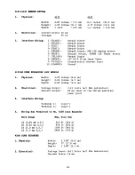
Page 65: ...Ready status Keypad Output 5V DC 20 mA Input Power Piezoelectric Sounder Input Ground Physical Width 3 25 inches 8 8 cm Height 2 63 inches 6 7 cm Depth 0 63 inches 1 6 cm Electrical Voltage Output 7 11 volts w l KHz modulation Current Output 65 mA part of the 400 mA auxiliary power pool Interface Wiring Terminal Terminal Wiring Run Permitted to Wire Gauge 22 0 64 mm O D 20 0 81mm O D 18 l Omm O D ...

Page 66: ...ion manual Passive Infrared Detectors do not provide volumetric area protection They do create multiple beams of protection and intrusion can only be detected in unobstructed areas covered by those beams They cannot detect motion or intrusion that takes place behind walls ceilings floors closed doors glass partitions glass doors or windows Mechanical tampering masking painting or spraying of any m...

Page 67: ...GINAL PURCHASE IN NO CASE SHALL SELLER BE LIABLE TO ANYONE FOR ANY CONSEOUENTIAL OR INCIDENTAL DAMAGES FOR BREACH OF THIS OR ANY OTHER WARRANTY EXPRESS OR IMPLIED OR UPON ANY OTHER BASIS OF LIABILllV WHATSOEVER EVEN IF THE LOSS OR DAMAGE IS CAUSED BY THE SELLER SOWN NEGLIGENCE OR FAULT Some slates do not allow limitations on how long an imphed warranty Iasls ortheexclusion or Ilmitatlon of incider...

Page 68: ...ALARM DEVICE MANUFACTURING CO A DIVISION OF PITTWAY CORPORATION 165 Eileen Way Syosset New York 11791 N441 O 9 88 Copyright 1988 PITTWAY CORPORATION ...

Reviews: