background image

Index

102

Adept Cobra s350 User’s Guide, Rev. A

Summary of Contents for Cobra s350

Page 1: ...Adept Cobra s350 Robot User s Guide...

Page 2: ......

Page 3: ...gust 2006 3011 Triad Drive Livermore CA 94551 USA Phone 925 245 3400 Fax 925 960 0452 Otto Hahn Strasse 23 44227 Dortmund Germany Phone 49 231 75 89 40 Fax 49 231 75 89 450 41 rue du Saule Trapu 91882...

Page 4: ...dept MV4 Adept MV 5 Adept MV 8 Adept NanoBonder EBS Adept NanoBonder LWS Adept NanoCell Adept NanoStage L1P2 Adept NanoStage L3 Adept NanoStage L3P2 Adept OC Adept SmartAmp Adept SmartAxis Adept Smart...

Page 5: ...red Safeguards 18 Safety Barriers 18 Impact and Trapping Points 19 Additional Safety Information 20 2 4 Risk Assessment 21 Exposure 21 Severity of Injury 21 Avoidance 22 CAT 1 Control System 22 2 5 In...

Page 6: ...ption of Connectors on MB 40R Interface Panel 36 4 3 MB 40R Operation 37 Status LED on MB 40R 37 Status Panel 38 Brake Release Button on MB 40R 38 Brake Release Connector 39 4 4 Connecting Digital I O...

Page 7: ...60 Ground Point on Robot Base 60 Ground Point on MotionBlox 40R 61 Robot Mounted Equipment Grounding 61 5 9 Installing User Supplied Safety Equipment 61 6 System Operation 63 6 1 Using the Brake Relea...

Page 8: ...ng Encoder Battery 80 8 6 Inspecting Timing Belts 83 9 Technical Specifications 85 9 1 Dimension Drawings 85 9 2 Robot Specifications 88 10 Cleanroom Robots 91 10 1 Cobra s350 CR ESD Cleanroom Option...

Page 9: ...gure 5 4 Single Phase AC Power Installation from a Three Phase AC Supply 58 Figure 5 5 AC Power Mating Connector 60 Figure 5 6 Ground Point on Robot Base 60 Figure 5 7 User Ground Location on MB 40R 6...

Page 10: ...ESD Cleanroom Robot 91 Figure 10 2 Cleanroom Connections 92 Figure 10 3 Cleanroom Lower Bellows Replacement 94 Figure 10 4 Cleanroom Upper Bellows Replacement 95 Figure 10 5 Adept Cobra s350 CR ESD To...

Page 11: ...age 12 for a description of the robot joint locations The Adept Cobra s350 robots require an Adept MotionBlox 40R and Adept SmartController The robots are programmed and controlled using the SmartCont...

Page 12: ...features Four AC servo motor amplifiers Category 3 emergency stop circuitry 200 MHz RISC microprocessor for high performance servo control 8 kHz servo rate delivers low positional errors and superior...

Page 13: ...integrated vision option and a conveyor tracking option as well as other options It offers scalability and support for IEEE 1394 based digital I O and general motion expansion modules The IEEE 1394 i...

Page 14: ...on page 53 4 Install the Arm Power Signal cable between the MB 40R and the robot See Section 5 5 on page 53 5 Create a 24 VDC cable and connect it between the MB 40R and the user supplied 24 VDC power...

Page 15: ...ate ADL CD shipped with your system the Adept Web site Select Document Library from the Adept home page To go directly to the Adept Document Library type the following URL into your browser http www a...

Page 16: ...Chapter 1 Introduction 16 Adept Cobra s350 User s Guide Rev A...

Page 17: ...ion emphasizes a point or procedure or gives a tip for easier operation DANGER This indicates an imminently hazardous situation which if not avoided will result in death or serious injury WARNING This...

Page 18: ...m entering the workcell whenever equipment power is present The robot system integrator or end user must ensure that adequate safeguards safety barriers light curtains safety gates safety floor mats e...

Page 19: ...ency power off circuitry is capable of switching external power systems and can be interfaced to the appropriate user supplied safeguards Impact and Trapping Points Adept robots are capable of moving...

Page 20: ...ards 389 Chiswick High Road London W4 4AL United Kingdom Phone 44 0 20 8996 9000 Fax 44 0 20 8996 7400 http www bsi global com Document Center Inc 1504 Industrial Way Unit 9 Belmont CA 94002 USA Phone...

Page 21: ...permitted exception is for teaching the robot in Manual Mode by a skilled programmer see Qualification of Personnel on page 26 who must wear safety equipment see Safety Equipment for Operators on pag...

Page 22: ...osure consideration factors European Standard EN 1050 specifies use of a Category 1 Control System per EN 954 EN 954 defines a Category 1 Control System as one that employs Category B components desig...

Page 23: ...ct with liquids The Adept equipment is not intended for use in any of the following situations In hazardous explosive atmospheres In mobile portable marine or aircraft systems In life support systems...

Page 24: ...robot These should be designed so they do not restrict joint motion or cause robot motion errors Unacceptable Modifications The modifications listed below may damage the robot reduce system safety and...

Page 25: ...ds For robot systems these include EN 775 ISO 10218 sections 5 6 EN 292 2 and EN 60204 For safety fences see EN 294 In other countries Adept strongly recommends in addition to complying with the appli...

Page 26: ...sonnel This manual assumes that all personnel have attended an Adept training course and have a working knowledge of the system The user must provide the necessary additional training for all personne...

Page 27: ...around the workcell to ensure that anyone working around the robot system knows they must wear safety equipment 2 14 Protection Against Unauthorized Operation The system must be protected against unau...

Page 28: ...ator can enter workcell with High Power ON Take precautions to ensure that these situations do not occur 2 17 What to Do in an Emergency Situation Press any E Stop button a red push button on a yellow...

Page 29: ...age from normal shock and vibration You should protect the package from excessive shock and vibration At least two people should transport and store the packaged equipment see Figure 3 1 The robots mu...

Page 30: ...eceipt Contact Adept as soon as possible If the items received do not match your order please contact Adept immediately Inspect each item for external damage as it is removed from its container If any...

Page 31: ...g locating pins could improve the ability to remove and reinstall the robot in the same position The Adept Cobra s350 robot can be mounted on a moving platform with proper attention paid to adequately...

Page 32: ...oning pin See Table 3 2 for bolt and torque specifications 2 Install a diamond shaped pin into the 4H7 diameter hole 3 Install an internally threaded positioning pin into the 6H7 hole 4 Turn the J2 ax...

Page 33: ...d against a harder surface Verify that the robot is mounted squarely will not rock back and forth before tightening the mounting bolts 8 Install the customer supplied mounting bolts and washers Tighte...

Page 34: ...Chapter 3 Robot Installation 34 Adept Cobra s350 User s Guide Rev A...

Page 35: ...unicate coordinate and execute servo commands The MB 40R consists of a distributed servo amplifier RISC processor for servo loop control a node on the FireWire Network a power controller that uses sin...

Page 36: ...ler XSYS connector DB 9 female SmartServo 1 2 for connecting the IEEE 1394 cable from the controller SmartServo 1 1 to the upper connector SmartServo 1 RS 232 Reserved for future use DB 9 male XPANEL...

Page 37: ...us of the robot See Table 4 1 Figure 4 3 Controls and Indicators on MB 40R Table 4 1 Status LED Definition LED Status Description Off 24 VDC not present Green Slow Blink High Power Disabled Green Fast...

Page 38: ...37 Under some circumstances you may want to manually position Joints 3 and 4 without turning on High Power You can use the Brake release button for this purpose When 24 V power is enabled pressing thi...

Page 39: ...elease button The digital inputs on this connector meet the same input level requirements as the XIO inputs See Table 4 7 on page 44 for details Table 4 3 Brake Release Connector Pinouts Pin Descripti...

Page 40: ...5 on page 42 Table 4 4 Digital I O Connection Options Product I O Capacity For more details XIO Connector on MB 40R 12 inputs 8 outputs see Section 4 5 on page 43 XDIO Connector on SmartController 12...

Page 41: ...YS CAMERA Eth 10 100 XUSR Device Net XFP RS 232 TERM RS 232 1 XMCP BELT ENCODER SmartController CX RS 422 485 XDC1 XDC2 24V 5A S N 3562 XXXXX RS 232 2 Optional sDIO 1 SmartController MB 40R Optional I...

Page 42: ...mended a a For sDIO modules 3 and 4 you must configure the signals using CONFIG_C to have the system support those modules See the Adept SmartController User s Guide for additional information on that...

Page 43: ...le 4 6 XIO Signal Designations Pin No Designation Signal Bank V Signal Number Pin Locations 1 GND XIO 26 pin female connector on MB 40R Interface Panel 2 24 VDC 3 Common 1 1 4 Input 1 1 1 1097 5 Input...

Page 44: ...e 43 or through the optional XIO Termination Block See the documentation supplied with the Termination Block for details The XIO inputs cannot be used for REACTI programming high speed interrupts or v...

Page 45: ...lied Equipment User Supplied Equipment Signal 1097 Part Present Sensor 4 Signal 1098 Feeder Empty Sensor 5 Signal 1099 Part Jammed Sensor 6 Signal 1100 Sealant Ready Sensor 7 Signal 1101 8 Signal 1102...

Page 46: ...ugh a self resetting polyfuse The outputs are accessed through direct connection to the XIO connector see Table 4 6 on page 43 or through the optional XIO Termination Block See the documentation suppl...

Page 47: ...the workcell The part number for the cable is 04465 000 and the length is 5 M 16 4 ft See Table 4 9 on page 48 for the wire chart on the cable NOTE this cable is not compatible with the XIO Terminatio...

Page 48: ...ow Black 7 Input 4 1 Green 8 Input 5 1 Green Black 9 Input 6 1 Blue 10 GND Blue White 11 24 VDC Brown 12 Common 2 Brown White 13 Input 1 2 Orange 14 Input 2 2 Orange Black 15 Input 3 2 Gray 16 Input 4...

Page 49: ...g Dimensions 0 425 5 20 6 204 2 404 9 51 6 331 7 9 8 0 228 6 67 3 222 3 106 7 182 9 170 2 6X SHCS M4 X 6 A B 0 47 6 377 8 0 7 6 45 7 129 54 C 0 32 7 197 8 0 7 6 45 7 C 0 32 7 197 8 0 7 6 45 7 C 0 47 6...

Page 50: ...Chapter 4 MotionBlox 40R 50 Adept Cobra s350 User s Guide Rev A...

Page 51: ...ower from User Supplied Power Supply to Controller XDC1 Desktop or Laptop PC Running AdeptWindows user supplied Terminator Installed User Supplied Ground Wire User Supplied Ground Wire External Brake...

Page 52: ...ound wire between the SmartController and ground 6 Install the AdeptWindows PC software on the user supplied PC Refer to the AdeptWindows Installation Guide This includes connecting the supplied Ether...

Page 53: ...erface panel XSLV safety interlock connector and XSYS connector on the SmartController and tighten the latching screws 5 5 Cable Connections from MB 40R to Robot Installing the Arm Power Signal Cable...

Page 54: ...wer supply must incorporate overload protection to limit peak power to less than 300 W or 8 A in line fuse protection must be added to the 24 V power source output must be less than 300 W peak or 8 Am...

Page 55: ...ler That cable uses a different style of connector See the Adept SmartController User s Guide 3 Crimp the pins onto the wires using the crimping tool recommended in Table 5 4 4 Insert the pins into th...

Page 56: ...NOTE In order to maintain compliance with EN standards Adept recommends that DC power be delivered over shielded cables with the shield connected to frame ground at the power supply and to the ground...

Page 57: ...t suppressor shall be capable of absorbing the energy in the transient In the industrial environment nonperiodic over voltage peaks may appear on mains power supply lines as a result of power interrup...

Page 58: ...allation from a Three Phase AC Supply E E N N L L F1 10A MB 40R 1 200 240 VAC User Supplied AC Power Cable Note F1 is user supplied must be slow blow 1 200 240 VAC 20A L Line N Neutral E Earth Ground...

Page 59: ...Loosen the two screws on the cable clamp See Figure 5 5 on page 60 4 Use 18 AWG wire to create the AC power cable Select the wire length to safely reach from the user supplied AC power source to the...

Page 60: ...nnector on the interface panel on the MB 40R 3 Secure the AC connector with the locking latch 5 8 Grounding the Adept Robot System Proper grounding is essential for safe and reliable robot operation F...

Page 61: ...he ground point on the robot base Hazardous voltages can be considered anything in excess of 30 VAC 42 4 VAC peak or 60 VDC See also Figure 9 3 on page 87 for the grounding point on the tool flange 5...

Page 62: ...Chapter 5 System Installation 62 Adept Cobra s350 User s Guide Rev A...

Page 63: ...d High Power has been removed In addition Joints 3 and 4 have electromechanical brakes The brakes are released when High Power is enabled When High Power is turned off the brakes engage and hold the p...

Page 64: ...ete details on working with AdeptWindows 4 Wait for the system to complete the boot cycle Once completed the system will return with a dot prompt and the following window should be displayed Figure 6...

Page 65: ...o Program the Robot To learn how to use and program the robot go to the V Operating System User s Guide to find information on basic operation of the V Operating System Also refer to the Instructions...

Page 66: ...Chapter 6 System Operation 66 Adept Cobra s350 User s Guide Rev A...

Page 67: ...age 60 NOTE A threaded hole is provided on the user flange The user may attach a ground wire through the quill connecting the outer link and the user flange 7 2 Removing and ReInstalling the User Flan...

Page 68: ...ighten the setscrew to finger tightness Do not over tighten the setscrew because this will cause the flange to be off center from the quill shaft 3 Tighten one of the M4 screws part of the way then ti...

Page 69: ...n the top of the outer link The maximum pressure for the air source is 0 59 MPa The Adept Cobra s350 is not equipped with solenoid valves Figure 7 2 User Air and Electrical Connectors on Robot 1 2 3 4...

Page 70: ...at CN21 See the Adept SmartController User s Guide for the electrical specifications for the signals from the XDIO connector Table 7 1 Mating Connectors for CN20 and CN21 Connector set part No Connec...

Page 71: ...Z axis shaft CAUTION Do not remove the mechanical end bolts on the 1st and 2nd axes or the mechanical stoppers on the 3rd axis see Figure 7 3 Also do not use these bolts and stoppers to secure a stay...

Page 72: ...the dimensions to fabricate the stay To install the stay attach four M3 bolts to the four threaded holes on the bottom of the outer arm to mount the stay The mounting holes are the same as those used...

Page 73: ...User Connections on Robot Adept Cobra s350 User s Guide Rev A 73 Figure 7 5 Dimensions for Fabricating User Supplied Stay 39 1 181 2x 22 98 2x 3 00 35 20 4 00 08 08 1 18 R 1 97...

Page 74: ...on and dimensions of the mounting holes See Figure 7 7 on page 75 and Figure 7 8 on page 76 for drawings of the brackets The user must fabricate this bracket it is not available from Adept An optional...

Page 75: ...Camera Bracket Drawing Page 1 of 2 5 01 010 A A 4 01 6 97 56 88 010 B B 3X UNLESS OTHERWISE SPECIFIED DIMENSIONS APPLY AFTER PROCESS INTERPRET DRAWING PER ANSI Y14 5 DIMENSIONS ARE IN INCHES TOLERANCE...

Page 76: ...91 89 DETAIL A 2 PLACES 1 AS SHOWN 1 MIRROR OPPOSITE R 1 75 3 45 54 2 362 900 43 THRU 4X M4X0 7 6H 38 ITEM 2 MOUNT CAMERA AL ALLOY 6061 T651 38 THK C L 1 00 2 00 81 MAX 2X R 12 B ITEM 1 BRACKET CAMER...

Page 77: ...Section 8 2 Check robot mounting bolts 3 months See Section 8 3 Lubricate Joint 3 Z axis ball screw 6 months See Section 8 4 Replace Encoder battery Every 2 years See Section 8 5 Inspect timing belts...

Page 78: ...xternal user supplied E Stop buttons 3 Test operation of barrier interlocks etc 8 3 Checking Robot Mounting Bolts Check the tightness of the base mounting bolts every 6 months Tighten to 70 N m 63 ft...

Page 79: ...the controller and robot Figure 8 1 Lubrication of Joint 3 Quill 2 Raise the Joint 3 quill shaft to the upper position 3 Apply grease to the entire shaft See Table 8 2 on page 78 for details 4 Move th...

Page 80: ...ply cable from the MB 40R 24 VDC input connector See Figure 4 2 on page 36 for locations of connectors 6 Disconnect the 200 240 VAC supply cable from the MB 40R AC input connector 7 Remove the battery...

Page 81: ...have disconnected the old one in the previous step and then load it into the holder See Figure 8 4 Figure 8 4 Installing First New Battery 10 Disconnect the remaining old battery 2nd one from the bat...

Page 82: ...d from which you have disconnected the old one in the previous step and then load it into the holder See Figure 8 6 Figure 8 6 Installing Second New Battery 12 Re install the cover on the robot unit T...

Page 83: ...ting Timing Belts This inspection should be done every 12 months 1 Turn off power to the SmartController and MB 40R 2 Visually inspect the timing belts for Joint 3 and Joint 4 for excessive wear or mi...

Page 84: ...Chapter 8 Maintenance 84 Adept Cobra s350 User s Guide Rev A...

Page 85: ...9 9 1 Dimension Drawings Figure 9 1 Adept Cobra s350 Top and Side Dimensions NOTE The supplied Adept flange sits 10 0 mm below the bottom of the quill shown in Figure 9 1 Work Area 75 75 60 60 0 4x 1...

Page 86: ...Adept Cobra s350 User s Guide Rev A Figure 9 2 Adept Cobra s350 Robot Working Envelope Max Radial Reach Functional Area R 350 mm Max Intrusion Contact Radius R 412 mm Cartesian Limits 175 mm Minimum...

Page 87: ...etail A Detail A 6 80 mm 0 268 in 1 5 mm 0 059 in 4 14 mm 0 163 in 12 0 mm 0 47 in 20 0 mm 0 79 in 3 0 mm 0 12 in 43 mm 1 69 in 30 25 45 41 15 mm 63 0 mm 2 48 in Dowel Pin Hole C B A 10 mm 004 in 50 0...

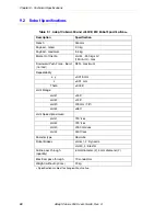
Page 88: ...nt of Inertia Joint 4 450 kg cm 150 lb in max Downward Push Force Burst no load 98 N maximum Repeatability x y 0 015 mm z 0 01 mm Theta 0 005 Joint Range Joint 1 155 Joint 2 145 Joint 3 200 mm 7 8 Joi...

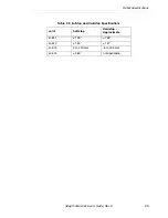
Page 89: ...ons Adept Cobra s350 User s Guide Rev A 89 Table 9 2 Softstop and Hardstop Specifications Joint Softstop Hardstop Approximate Joint 1 155 158 Joint 2 145 147 Joint 3 0 to 200 mm 5 to 205 mm Joint 4 36...

Page 90: ...Chapter 9 Technical Specifications 90 Adept Cobra s350 User s Guide Rev A...

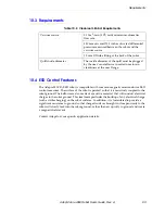
Page 91: ...l Standard 209E as well as special requirements for control of Electrostatic Discharges to the robot surface NOTE Federal Class 1 Limits ISO 3 can be achieved by running the robot at lower speeds and...

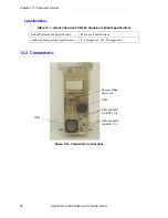
Page 92: ...Figure 10 2 Cleanroom Connections Table 10 1 Adept Cobra s350 CR ESD Cleanroom Robot Specifications Robot Performance Specification Same as standard robot Ambient Temperature Specification 5 35 degre...

Page 93: ...addition it is formulated to provide a significant resistance to ground so that charged surfaces brought in close proximity to the robot will slowly leak into the robot ground rather than arc quickly...

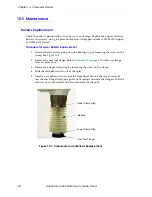
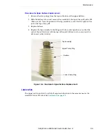
Page 94: ...osening the screw on the clamp See Figure 10 3 2 Remove the user tool flange Refer to Section 7 2 on page 67 for the user flange removal procedure 3 Remove the upper clamp ring by loosening the screw...

Page 95: ...he split nut lies just at the top of the quill 3 Replace bellows 4 Replace the top assembly to the flange with the vertical position set so that the split of the nut lies level with the top of the qui...

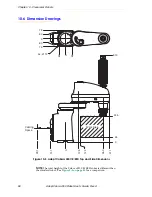
Page 96: ...awings Figure 10 5 Adept Cobra s350 CR ESD Top and Side Dimensions NOTE The total height of the Cobra s350 CR ESD robot is different than the standard robot See Figure 9 1 on page 85 for a comparison...

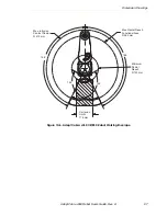
Page 97: ...Robot User s Guide Rev A 97 Figure 10 6 Adept Cobra s350 CR ESD Robot Working Envelope Max Radial Reach Functional Area R 350 mm Max Intrusion Contact Radius R 412 mm Cartesian Limits 175 mm Minimum R...

Page 98: ...Chapter 10 Cleanroom Robots 98 Adept Cobra s350 Robot User s Guide Rev A...

Page 99: ...cription 74 dimensions for mounting holes 74 user supplied bracket dimensions 75 circuit protection 24 VDC power 54 Cleanroom robot connections 92 description 91 ESD control features 93 lubrication 95...

Page 100: ...type of grease for robot 78 M maintenance checking safety systems 78 lubricating Joint 3 78 replacing bellows on Cleanroom robot 94 replacing encoder battery 80 schedule 77 MB 40R brake release button...

Page 101: ...ces for international standards and directives 20 specifications 24VDC power 54 AC power 57 robot 88 status LED description 37 status panel codes on MB 40R 38 stay user supplied 73 storage information...

Page 102: ...Index 102 Adept Cobra s350 User s Guide Rev A...

Page 103: ......

Page 104: ...3011 Triad Drive Livermore CA 94551 925 245 3400 P N 05624 000 Rev A...

Reviews: