background image

Chapter 8 - Technical Specifications

108

Adept Cobra s600/s800 Robot User’s Guide, Rev H

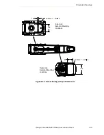
Figure 8-4. Tool Flange Dimensions for Adept Cobra Robots

4X  M6 x 1- 6H Thr

u

User Gro

u

nd

See Detail A

Detail A

6.

8

0 mm

(0.26

8

 in.)

1.5 mm
(0.059 in.)

4.14 mm
(0.163 in.)

12.0 mm
(0.47 in.)

20.0 mm
(0.79 in.)

3.0 mm
(0.12 in.)

43 mm
(1.69 in.)

30

˚

25

˚

45˚

 41.15 mm

∅ 

63.0 mm (2.4

8

 in.)

Dowel Pin Hole 

C

B

A

.10 mm (.004 in.)

50.0 mm (1.96

8

5 in.)

BC

∅ 

6.0 mm

-C-

-A-

-B-

+.03 mm
–.00 mm

(

 1.620 in.) (+.001 in.)

(–.000 in.)

M

M

M

R 3.56mm (R 0.140in) 
   5.0

8

mm (0.20in) 

M3 X 0.5-6H Thr

u

(0.2362 in.)

+.01 mm 
– 0 mm

(+.0005 in.)
(– 0  in.)

Summary of Contents for Cobra s600

Page 1: ...Adept Cobra s600 s800 Robot User s Guide...

Page 2: ......

Page 3: ...5960 Inglewood Drive Pleasanton CA 94588 USA Phone 925 245 3400 Fax 925 960 0452 Otto Hahn Strasse 23 44227 Dortmund Germany Phone 49 231 75 89 40 Fax 49 231 75 89 450 Block 5000 Ang Mo Kio Avenue 5 0...

Page 4: ...obra Smart600 Adept Cobra Smart800 Adept DeskTop Adept FFE Adept FlexFeeder 250 Adept IC Adept iSight Adept Impulse Feeder Adept LineVision Adept MB 10 ServoKit Adept MC Adept MotionBlox 10 Adept Moti...

Page 5: ...abels on the Robot 22 2 3 Precautions and Required Safeguards 23 Safety Barriers 24 Front Panel Location 24 Impact and Trapping Points 24 Instructions for Emergency Movement without Drive Power 24 Eme...

Page 6: ...ty Requirements 37 3 5 Mounting the Robot 37 Mounting Surface 37 Robot Mounting Procedure 38 3 6 Description of Connectors on Robot Interface Panel 40 4 System Installation 41 4 1 System Cable Diagram...

Page 7: ...pecifications 60 Typical Input Wiring Example 61 XIO Output Signals 62 XIO Output Specifications 62 Typical Output Wiring Example 63 XIO Breakout Cable 63 5 6 Commissioning the System 65 Verifying Ins...

Page 8: ...nectors 84 SOLND Connector 85 OP3 4 Connector 85 EOAPWR Connector 86 Internal User Connector Output Specifications 87 ESTOP Connector 88 Procedure to Enable Breakaway E Stop Function 88 7 5 Mounting L...

Page 9: ...ance 119 Bellows Replacement 119 Lubrication 120 10 IP 65 Option 121 10 1 Cobra s800 IP 65 Classification 121 10 2 Installing Cable Seal Assembly 122 Cable Seal Identification 122 Installation Procedu...

Page 10: ...O Outputs 137 XIO Inputs 137 Internal Robot Outputs 137 IO Blox Inputs Outputs 137 sDIO Inputs Outputs 137 11 5 Using CONFIG_C to Configure I O 140 IO Configuration by Editing System File 140 IO Confi...

Page 11: ...Figure 5 1 Robot Status LED Indicator Location 53 Figure 5 2 Status Panel 54 Figure 5 3 Connecting Digital I O to the System 57 Figure 5 4 Typical User Wiring for XIO Input Signals 61 Figure 5 5 Typic...

Page 12: ...gure 8 3 Dimensions of the Camera Bracket Mounting Pattern 107 Figure 8 4 Tool Flange Dimensions for Adept Cobra Robots 108 Figure 8 5 External Tooling on Top of Robot Arm 109 Figure 8 6 External Tool...

Page 13: ...3 Figure 11 2 Digital I O Connections to a Dual Robot System 135 Figure 11 3 Input Output Block Configuration in Dual Robot Systems 138 Figure 11 4 Input Output Block Configuration for Optional sDIO M...

Page 14: ......

Page 15: ...Adept Cobra s series robots require an Adept SmartController The robots are programmed and controlled using the SmartController running on the Adept SmartServo distributed motion control platform Mech...

Page 16: ...tures On board digital I O Low EMI for use with noise sensitive equipment No external fan for quiet robot operation 8 kHz servo rate delivers low positional errors and superior path following Sine wav...

Page 17: ...ed controls architecture supporting Adept products The controller also includes Fast Ethernet and DeviceNet Figure 1 4 Adept SmartController CX Adept SmartController CX The Adept SmartController CX is...

Page 18: ...37 2 Install the SmartController Front Panel pendant and AdeptWindows user interface See Section 4 3 on page 42 3 Install the IEEE 1394 and XSYS cables between the robot and SmartController See Secti...

Page 19: ...he menu bar on the Adept website home page adept com or Type the following URL into your web browser http www adept com Main KE DATA adept_search htm To locate information on a specific topic use the...

Page 20: ......

Page 21: ...us electrical situation which if not avoided will result in death or serious injury DANGER This indicates an imminently hazardous situation which if not avoided will result in death or serious injury...

Page 22: ...Guide Rev H 2 2 Warning Labels on the Robot The following two figures show the warning labels on the Adept Cobra s series robots Figure 2 1 Electrical and Thermal Warning Labels on AIB Chassis Figure...

Page 23: ...e Do not remove the J3 ENC or J4 ENC encoder cable connectors from their sockets If they are removed the calibration data will be lost and the robot must be run through a factory recalibration process...

Page 24: ...system safeguards including emergency stop circuitry and digital input and output lines The emergency power off circuitry is capable of switching external power systems and can be interfaced to the a...

Page 25: ...nsi org Underwriters Laboratories Inc 333 Pfingsten Road Northbrook IL 60062 2096 USA Phone 1 847 272 8800 Fax 1 847 272 8129 http www ul com info standard htm BSI Group British Standards 389 Chiswick...

Page 26: ...oduct based on the intended applications of the robot The conclusions are summarized below DIN Deutsches Institut f r Normung e V German Institute for Standardization Burggrafenstrasse 6 10787 Berlin...

Page 27: ...ight normally reversible Avoidance A programmer must always carry the pendant when inside the work envelope as the pendant provides both E Stop and Enabling switch functions For normal operation AUTO...

Page 28: ...magnetic Compatibility EMC In situations with low exposure consideration factors European Standard EN 1050 specifies use of a Category 1 Control System per EN 954 EN 954 defines a Category 1 Control S...

Page 29: ...lations In situations where the Adept equipment will be subject to extremes of heat or humidity See Table 3 1 on page 37 for allowable temperature and humidity ranges Non intended use of an Adept Cobr...

Page 30: ...rors Unacceptable Modifications The modifications listed below may damage the robot reduce system safety and reliability or shorten the life of the robot Modifying any of the robot harnesses or robot...

Page 31: ...dition to complying with the applicable local and national regulations that a similar level of safety be obtained In the USA applicable standards include ANSI RIA R15 06 and ANSI UL 1740 In Canada app...

Page 32: ...The user must provide the necessary additional training for all personnel who will be working with the system As noted in this manual certain procedures should be performed only by skilled or instruc...

Page 33: ...to prevent access to them 2 15 Safety Aspects While Performing Maintenance Only skilled persons with the necessary knowledge about the safety and operation of the equipment are allowed to maintain the...

Page 34: ...les other than those supplied or use of modified components in the system Defeating interlock so that operator can enter workcell with High Power ON Take precautions to ensure that these situations do...

Page 35: ...ct the package from excessive shock and vibration Use a forklift pallet jack or similar device to transport the packaged equipment see Figure 3 1 The robots must always be stored and shipped in an upr...

Page 36: ...ipt Contact Adept as soon as possible If the items received do not match your order please contact Adept immediately Inspect each item for external damage as it is removed from its container If any da...

Page 37: ...nting flexure will degrade robot performance Figure 3 2 shows the mounting hole pattern for the Adept Cobra s series robots NOTE On the under side of the base there is a hole and a slot that can be us...

Page 38: ...op of the inner link see Figure 3 1 on page 35 Take up any slack but do not lift the robot at this time 3 Remove the four bolts securing the robot base to the pallet Retain these bolts for possible la...

Page 39: ...the mounting bolts 7 Install the user supplied mounting bolts and washers Tighten bolts to the torque specified in Table 3 2 NOTE Check the tightness of the mounting bolts one week after initial insta...

Page 40: ...94 cable from the controller SmartServo 1 1 to the robot upper connector SmartServo 1 The robot lower connector SmartServo 2 can be used to connect to a second robot or another 1394 based motion axis...

Page 41: ...ler Adept Cobra s600 s800 Robot User Supplied 24VDC Power Supply User Supplied 200 240 VAC single phase Controller XFP to Front Panel XFP Front Panel XSYS Cable Controller XSYS to Robot XSLV 24VDC Pow...

Page 42: ...e Adept software PC user interface Refer to the AdeptWindows Installation Guide or appropriate manual Table 4 1 Cable and Parts List Part Description Part Number Notes IEEE 1394 Cable 4 5 M 10410 0054...

Page 43: ...a 24 V 6 A power supply to allow for startup current draw and load from connected user devices such as solenoids and digital I O loads If multiple robots are to be sourced from a common 24 V power sup...

Page 44: ...obot base NOTE You also must create a separate 24 VDC cable for the SmartController That cable uses a different style of connector See the Adept SmartController User s Guide 3 Crimp the pins onto the...

Page 45: ...ble into the 24 VDC connector on the interface panel on the back of the robot The cable shield should be connected to the ground point on the interface panel Figure 4 2 User Supplied 24 VDC Cable NOTE...

Page 46: ...tions for 200 240 VAC User Supplied Power Supply Auto Ranging Nominal Voltage Ranges Minimum Operating Voltagea a Specifications are established at nominal line voltage Low line voltage can affect rob...

Page 47: ...eed overvoltage Category II i e not higher than the impulse voltage corresponding to the rated voltage for the basic insulation The user supplied equipment or transient suppressor shall be capable of...

Page 48: ...upplied with the system but is available in the optional Power Cable kit see Table 4 1 on page 42 Table 4 7 AC Mating Connector Details AC Connector details AC in line power plug straight female screw...

Page 49: ...rt the wires into the connector through the removable bushing 7 Connect each wire to the correct terminal screw and tighten the screw firmly 8 Tighten the screws on the cable clamp 9 Replace the cover...

Page 50: ...Robot Base Robot Mounted Equipment Grounding The following parts of an Adept Cobra s600 s800 robot are not grounded to protective earth the Joint 3 quill and the tool flange If hazardous voltages are...

Page 51: ...Depending on the design of the workcell safety gates light curtains and emergency stop devices can be used to create a safe environment Read Chapter 2 in this manual for a discussion of safety issues...

Page 52: ......

Page 53: ...layed by this LED Legacy models have a bi color red and green LED See Table 5 2 for the status information displayed by this LED Figure 5 1 Robot Status LED Indicator Location Table 5 1 Status LED Def...

Page 54: ...ter the fault is corrected or additional faults are recorded All displayed faults will be cleared from the display and reset to a no fault condition upon successfully enabling high power to the robot...

Page 55: ...not prevent you from moving the robot manually once the robot has stopped and High Power has been removed In addition Joint 3 has an electromechanical brake The brake is released when High Power is en...

Page 56: ...g this button releases the brake which allows movement of Joint 3 If this button is pressed while High Power is on High Power will automatically shut down WARNING Due to the effect of gravity pressing...

Page 57: ...uts per device up to four IO Blox devices per robot see Adept IO Blox User s Guide Optional sDIO Module connects to controller 32 inputs 32 outputs per module up to four sDIO per system see Adept Smar...

Page 58: ...dules 3 and 4 you must configure the signals using CONFIG_C to have the system support those modules See the Adept SmartController User s Guide for additional information on that process Inputs 1201 1...

Page 59: ...4 Table 5 6 XIO Signal Designations Pin No Designation Signal Bank V Signal Number Pin Locations 1 GND XIO 26 pin female connector on Robot Interface Panel 2 24 VDC 3 Common 1 1 4 Input 1 1 1 1097 5 I...

Page 60: ...n page 59 or through the optional XIO Termination Block See the documentation supplied with the Termination Block for details The XIO inputs cannot be used for REACTI programming high speed interrupts...

Page 61: ...Supplied Equipment User Supplied Equipment Signal 1097 Part Present Sensor 4 Signal 1098 Feeder Empty Sensor 5 Signal 1099 Part Jammed Sensor 6 Signal 1100 Sealant Ready Sensor 7 Signal 1101 8 Signal...

Page 62: ...bot through a self resetting polyfuse The outputs are accessed through direct connection to the XIO connector see Table 5 6 on page 59 or through the optional XIO Termination Block See the documentati...

Page 63: ...s in the workcell The part number for the cable is 04465 000 and the length is 5 M 16 4 ft See Table 5 9 on page 64 for the wire chart on the cable NOTE this cable is not compatible with the XIO Termi...

Page 64: ...1 Yellow Black 7 Input 4 1 Green 8 Input 5 1 Green Black 9 Input 6 1 Blue 10 GND Blue White 11 24 VDC Brown 12 Common 2 Brown White 13 Input 1 2 Orange 14 Input 2 2 Orange Black 15 Input 3 2 Gray 16...

Page 65: ...that any end of arm tooling is properly installed Verify that all other peripheral equipment is properly installed and in a state where it is safe to turn on power to the robot system System Cable Ch...

Page 66: ...h a dot prompt and the following window should be displayed Figure 5 7 Typical Startup Screen 6 There should be no errors if the boot sequence completed successfully 7 Disengage any E Stops 8 Manually...

Page 67: ...out Verify Robot Motions Use the pendant to test the motion of each axis on the robot to confirm it moves in the proper directions Refer to the Adept SmartController User s Guide the T1 Pendant User s...

Page 68: ......

Page 69: ...nce on page 119 for cleanroom robots and Customer Requirements on page 126 for IP 65 robots Table 6 1 Field replaceable Parts Part Adept Part Number Encoder battery 02704 000 3 6 V 8 5 Ah AIB Amp In B...

Page 70: ...of any external user supplied E Stop buttons 3 Test operation of barrier interlocks etc Check for signs of oil around of harmonic drive area 3 months See Section 6 5 Lubricate Joint 3 Z axis ball scr...

Page 71: ...s of oil in areas immediately outside of the harmonic drive Check these locations the area around Joint 1 the area around Joint 2 inside the base of the robot by opening the AIB chassis and inspecting...

Page 72: ...se to the three vertical grooves and the spiral groove 6 Press the brake button and move Joint 3 to the bottom of its travel Remove any existing grease with a clean lint free soft cloth 7 Apply a smal...

Page 73: ...tion of Joint 3 Quill Joint 3 Ball Screw Lubrication Points A A Section A A Top View Looking Down Quill Shaft Vertical Groove Lube Point A Vertical Groove Lube Point B Vertical Groove Lube Point C Upp...

Page 74: ...sis XSLV connector 7 Disconnect the 1394 cable from the chassis SmartServo connector 8 Disconnect any other cables which may be connected to the chassis such as XIO RS 232 or any others 9 Using a 5 mm...

Page 75: ...y disengaging the securing latches 13 Carefully disconnect the J11 cable from the J11 connector on the PMAI by disengaging the securing latches 14 Carefully disconnect the J27 cable from the J27 conne...

Page 76: ...from inside the chassis 2 Carefully place the chassis next to the robot 3 Using a 5 mm Allen wrench carefully connect the ground wire to the chassis 4 Carefully connect the J28 cable to the J28 connec...

Page 77: ...ssis securing screw See Figure 6 2 on page 74 for details 11 Connect the 200 240 VAC supply cable to the chassis AC input connector 12 Connect the XSLV cable to the chassis XSLV connector 13 Connect t...

Page 78: ...Obtain the replacement battery 2 Switch off the SmartController 3 Switch off the 24 VDC input supply to the robot 4 Switch off the 200 240 VAC input supply to the robot 5 Disconnect the 24 VDC supply...

Page 79: ...to the connectors on the secondary battery cable Make sure to verify the positive and negative connections are correct 12 Once the new battery is connected disconnect and remove the original battery...

Page 80: ......

Page 81: ...ting the outer link and the tool flange 7 2 Removing and Installing the Tool User Flange The tool flange can be removed and reinstalled If the flange is removed it must be reinstalled in exactly the s...

Page 82: ...ew is lined up with the original vertical groove 3 Support the flange while using a 2 5 mm Allen wrench to tighten the setscrew to finger tight Do not over tighten the setscrew because this will cause...

Page 83: ...ide for details User Electrical Lines There is a 25 pin male connector 24 conductor on the robot user panel on the back of Joint 1 for user electrical lines see Figure 7 2 This connector is wired dire...

Page 84: ...ESTOP Figure 7 5 SOLND Connector WARNING When the Outer link cover is removed you see the label shown above Do not remove the J3 ENC or J4 ENC encoder cable connectors from their sockets If they are...

Page 85: ...86 Table 7 1 SOLND Connector Pinout Pin Description Pin Location 1 Output 3001 signal 9 in Cobra i600 i800 robots SOLND Connector as viewed on robot 2 Ground 3 Output 3002 signal 10 in Cobra i600 i800...

Page 86: ...current specs EOAPWR Connector as viewed on robot 2 Ground 3 24 VDC see Table 7 4 for current specs 4 Ground Mating Connector AMP Tyco 172167 1 4 pin Mini Universal Mate N Lok AMP Tyco 770985 1 Pin C...

Page 87: ...0 mA Total Current Limitation all channels on a a Note Total current is the sum of the output current used by output signals 3001 3004 SOLND and OP3 4 and any user current drawn from EOAPWR Itotal 1 0...

Page 88: ...Procedure to Enable Breakaway E Stop Function To enable the Breakaway E Stop function you have to use the SPEC utility to change the default configuration 1 At the V prompt type load util spec When t...

Page 89: ...mally closed circuit to pins 1 and 2 of the ESTOP connector as described above If this is not done the system will be in an E Stop condition and you will not be able to enable power 7 5 Mounting Locat...

Page 90: ...plies air at the user s line pressure minimum 28 psi 0 19 MPa to maximum 114 psi 0 786 MPa Each valve has two output ports A and B The output ports are arranged so that when Port A is pressurized Port...

Page 91: ...he air intake coupling of the solenoid manifold Make sure the air line is pushed in all the way and secured in place by the intake coupling Confirm by gently pulling the air line NOTE If you are insta...

Page 92: ...ill Use cable ties as needed to secure the tubing 10 Loosen the securing screw on the AIB chassis and lower the chassis down flat See Figure 6 2 on page 74 for the location of the securing screw 11 Re...

Page 93: ...uses after this modification 16 Replace the Joint 1 cover taking care to ensure that all tubing is inside the cover and nothing gets crimped or pinched while pushing the cover into position Replace fo...

Page 94: ...dure 1 Install the camera plate to the outer link with four M5 X 12 mm screws see Figure 7 12 on page 95 as you perform this procedure 2 Install the two camera brackets to the camera plate with two st...

Page 95: ...pt Cobra s series robot Female connector for the robot tower Micro style 12 mm thread DIN female connector see Figure 7 3 on page 83 and Figure 7 13 on page 96 Male Micro style 12 mm thread DIN connec...

Page 96: ...installation See the Instructions for Adept Utility Programs for software setup Recommended Vendors for Mating Cables and Connectors A variety of vendors have molded cable assemblies for the Micro st...

Page 97: ...2 See Figure 7 14 Figure 7 14 Joint 1 Adjustable Hardstops Installation Procedure 1 Remove the plug from desired threaded hole Position 1 or 2 on each side of the robot 2 Install the adjustable hards...

Page 98: ...Program Main Menu 3 In the next menu select option 3 Edit joint motion specs See Figure 7 16 Figure 7 16 Robot Specs Menu 4 The system should go to the menu for Joint 1 verify this at the top of the s...

Page 99: ...next menu enter the new value for the J1 lower limit softstop See Table 7 7 for recommended softstop values for Position 1 or Position 2 Note that this value must be a negative number Figure 7 18 Join...

Page 100: ...select option 7 Save ALL specifications to system disk 10 Reboot the system by cycling 24 VDC power to the SmartController The new joint limits will be in affect when the system reboot is done Joint...

Page 101: ...7 22 on page 101 Figure 7 21 Joint 2 Adjustable Hardstop Locations Figure 7 22 Screw Locations for Joint 2 Adjustable Hardstops Joint 2 Adjustable Hardstop Plates Installed in Position 1 12 thru holes...

Page 102: ...Device for Joint 2 4 Use a 3 mm Allen wrench to install two supplied M4 x 10 screws to secure the hardstop device Tighten the screws to a torque of 2 5 N m 22 in lb Modifying Joint Limit Softstop Loc...

Page 103: ...J2 lower limit softstop See Table 7 8 for recommended softstop values for Position 1 Note that this value must be a negative number 7 In the next menu select option 5 upper joint limit See Figure 7 26...

Page 104: ...or the J2 upper limit softstop See Table 7 8 on page 103 9 Once you have modified the upper and lower joint limit softstops you must save the new values Select option 0 Exit then select option 7 Save...

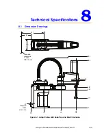
Page 105: ...Rev H 105 Technical Specifications 8 8 1 Dimension Drawings Figure 8 1 Adept Cobra s600 Robot Top and Side Dimensions 934 888 387 342 177 0 600 325 0 234 46 37 417 183 200 Required clearance to open...

Page 106: ...ns 106 Adept Cobra s600 s800 Robot User s Guide Rev H Figure 8 2 Adept Cobra s800 Robot Top and Side Dimensions Required clearance to open AIB Chassis 31 Required cable clearance 417 183 200 918 894 3...

Page 107: ...obra s600 s800 Robot User s Guide Rev H 107 Figure 8 3 Dimensions of the Camera Bracket Mounting Pattern Cobra s i600 4X M4x0 7 6H Cobra s i800 4X M4x0 7 6H 10 03 6 10 45 3 0 3 0 Cobra s i600 2X 54 8...

Page 108: ...Ground See Detail A Detail A 6 80 mm 0 268 in 1 5 mm 0 059 in 4 14 mm 0 163 in 12 0 mm 0 47 in 20 0 mm 0 79 in 3 0 mm 0 12 in 43 mm 1 69 in 30 25 45 41 15 mm 63 0 mm 2 48 in Dowel Pin Hole C B A 10 mm...

Page 109: ...dept Cobra s600 s800 Robot User s Guide Rev H 109 Figure 8 5 External Tooling on Top of Robot Arm 25 105 4X M4x0 7 6H 8 60 105 4X M4x0 7 6H 6 Inner Link External Mounting Locations Outer Link External...

Page 110: ...Technical Specifications 110 Adept Cobra s600 s800 Robot User s Guide Rev H Figure 8 6 External Tooling on Underside of Outer Link Outer Link Bottom View 76 Cobra s i600 135 Cobra s i800 4X M4x0 7 6H...

Page 111: ...Guide Rev H 111 Figure 8 7 Adept Cobra s600 Robot Working Envelope Maximum Radial Reach Functional Area 600 mm 23 62 in Maximum Intrusion Contact Radius 647 mm 25 50 in Minimum Radial Reach 162 6 mm 6...

Page 112: ...t User s Guide Rev H Figure 8 8 Adept Cobra s800 Robot Working Envelope Maximum Radial Reach Functional Area 800 mm 31 50 in Maximum Intrusion Contact Radius 847 3 mm 33 36 in Minimum Radial Reach 163...

Page 113: ...2 4 HIPWRDIS High Power Disable 5 ESTOP_RESET Normally Closed Check Contacts 6 AUTO1 ESTOP Auto Input Ch 1 7 AUTO2 ESTOP Auto Input Ch 2 8 N C 9 ESTOP_SRC ESTOP System 24 V Mating Connector AMP Tyco...

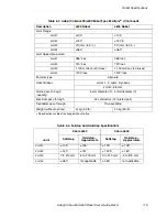
Page 114: ...Push Force Burst 178 N 40 lb maximum 133 N 30 lb maximum Adept Cycle Sustained no J4 rotation 0 kg 0 42 sec at 20 C 0 48 sec at 40 C 0 48 sec at 20 C 0 51 sec at 40 C 2 kg 0 45 sec at 20 C 0 51 sec at...

Page 115: ...quantity 6 mm diameter 2 4 mm diameter 3 Electrical pass through 24 conductors 12 twisted pair DeviceNet pass through One available Weight without options 41 kg 90 lb 43 kg 95 lb a Specifications sub...

Page 116: ......

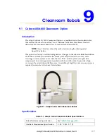
Page 117: ...y installed configuration Changes to the robot include the addition of a bellows assembly mounted at the Joint 3 quill fully sealed access covers and a two stage vacuum system to evacuate the arm This...

Page 118: ...vacuum source 3 4 inch NPT female thread pipe fitting at the back of the robot Compressed air source Clean dry oil free compressed air 75 psi 0 52 MPa 1 4 SCFM 04 m3 min flow rate 3 8 inch NPT female...

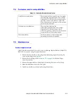
Page 119: ...sening the screw on the clamp 4 Slide the old bellows down off of the quill 5 Install a new bellows and reverse the steps listed above Table 9 3 Internally Mounted Hand Valves Installation considerati...

Page 120: ...de Rev H Figure 9 3 Cleanroom Bellows Replacement Lubrication The upper and lower quill requires lubrication in the same manner as the standard Cobra s600 s800 robots See Section 6 6 on page 71 Upper...

Page 121: ...side the robot shell against ingress of solid foreign objects Specifically for IP 65 Dust Protection No ingress of dust is allowed Water Resistance protection of the equipment inside the robot shell a...

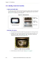
Page 122: ...cable seal parts Installation Procedure 1 Disassemble the cable seal assembly into separate pieces by removing all screws 2 Install the cable seal housing on the back of the robot using four M4x50 sc...

Page 123: ...ed position 5 Seat all of the cables by pushing down into the foam on the lower flange 6 Attach the upper flange to the lower flange using two M6 x 20 screws two M6 lock washers and two M6 flat washer...

Page 124: ...ve 2 screws and nylon washers on the top of the outer link 5 Remove 2 screws one on each side at the front of the outer link Make sure the o ring on each screw stays in place and is not lost 6 For the...

Page 125: ...r the cover down onto the outer link making sure the o ring does not fall out or get pinched as the cover presses down to make the seal NOTE As you lower the cover down onto the outer link make sure t...

Page 126: ...cted periodically to make sure these requirements are being met as part of a periodic maintenance program Sealing the Tool Flange The tool flange must be sealed so that the robot shell can be positive...

Page 127: ...e air fitting The specification for the regulated air supply is shown in Table 10 1 Table 10 1 Compressed Air Specifications Required Air Pressure Required Air Flow Minimum 3 bar 10 44 PSI 10 57 liter...

Page 128: ...ser electrical connector DB 25 and the IO Blox connector DB 9 on the back of the Joint 1 cover require a gel seal gasket to maintain an adequate seal The gaskets are supplied in the accessory kit Figu...

Page 129: ...ide positive airflow pressure to the bellows outer link You can use one of the passive 6 mm user air lines shown in Figure 10 12 and Figure 10 13 on page 128 10 6 Maintenance IP 65 Bellows Replacement...

Page 130: ...ring ring just above the user flange Align the mating surfaces of the clamp half rings with the bellows seam see Figure 10 15 Tighten the screw to secure the clamp Figure 10 14 Bellows Replacement Not...

Page 131: ...a s600 s800 Robot User s Guide Rev H 131 10 7 Dimension Drawing for Cable Seal Assembly Figure 10 16 Cable Seal Assembly Dimensions REQUIRED CLEARANCE TO OPEN AIB CONTROLLER WITH THE IP65 CONNECTOR CA...

Page 132: ......

Page 133: ...IEEE 1394 cable IEEE 1394 cable Adept SmartController Adept Cobra s600 s800 Robot 1 Adept Cobra s600 s800 Robot 2 User Supplied 24VDC Power Supply User Supplied 200 240 VAC single phase User Supplied...

Page 134: ...ation procedure are 1 Install the robots and controller as per the diagram in Figure 11 1 on page 133 NOTE The procedure below is only required if your system was not configured for dual robots at the...

Page 135: ...1 1 1 2 XDC1 XDC2 X3 1 2 3 RS 422 485 XUSR XSYS SF XMCP 1 1 SmartController CS LAN HPE OFF 24V 5A ON RS 232 TERM XFP HD ES XDIO Eth 10 100 S N 3561 XXXXX SW1 Device Net IEEE 1394 XDC1 XDC2 1 2 3 4 OK...

Page 136: ...es See the Adept SmartController User s Guide for additional information on that process Inputs 1201 1232 Outputs 0201 0232 sDIO Module 4 recommended a Inputs 1233 1264 Outputs 0233 0264 Robot 1 XIO c...

Page 137: ...the first output block XIO Inputs XIO inputs are mapped starting at 1097 for robot 1 and 1145 for robot 2 The first 2 bytes are allocated as follows 1st Cobra 1097 1108 on Block 1 2nd Cobra 1145 1156...

Page 138: ...Blox 3 IO Blox 4 0121 128 0129 136 Byte 3 Byte 4 IO Blox 1 Byte 1 Byte 2 1113 1120 IO Blox 2 1121 1128 IO Blox 3 IO Blox 4 1129 1136 1137 1144 Byte 3 Byte 4 Input Block 3 ROBOT 2 XIO Input Block 2 Byt...

Page 139: ...ended but must be configured using CONFIG_C so that the system will support those modules 0073 0080 0081 0088 0089 0096 Byte 3 Byte 4 Input Block 17 Byte 1 Byte 2 1065 1072 1073 1080 1081 1088 1089 10...

Page 140: ...hat was not configured at the factory or combining two formerly single robots then you will need to go through the configuration process There are two methods for configuring the I O IO configuration...

Page 141: ...on 2 Edit system configuration The following will be displayed Figure 11 7 System Configuration Editor Menu 5 Configure the I O as shown in Figure 11 8 on page 142 showing an example from a CONFIG_C f...

Page 142: ...NAL 1185 INPUT_BLOCK 4 INPUT_BYTE 4 IO_OPTIONAL YES VIS_TRIGGER 1 SIGNAL NONE VIS_TRIGGER 2 SIGNAL NONE DIGITAL_OUTPUT SIGNAL 33 OUTPUT_BLOCK 16 OUTPUT_BYTE 1 IO_OPTIONAL YES SIGNAL 41 OUTPUT_BLOCK 16...

Page 143: ...oading and executing CONFIG_C as shown in Figure 11 5 on page 140 2 In Figure 11 6 on page 141 select option 4 Import configuration data 3 Follow the instructions to import the file that you downloade...

Page 144: ...11 8 Programming Information V Language Programming By default Task 0 is used to control robot 1 Task 1 is normally recommended for robot 2 Use the SELECT ROBOT 2 and ATTACH instructions in your prog...

Page 145: ...robot is affected The most common system messages are described in the V Operating System User s Guide A full list of system messages with complete explanation and suggested user actions is in the V L...

Page 146: ......

Page 147: ...installing on IP 65 robot 122 camera bracket installation 94 kit 94 mounting pattern dimensions 107 circuit protection 24VDC power 43 45 Cleanroom robot connections 118 description 117 exclusions and...

Page 148: ...s specifications 115 hardstops adjustable for J1 J2 97 How Can I Get Help 19 I IEEE 1394 cable 40 42 43 impact and trapping points 24 installation 24VDC power to robot 43 AC power to robot 49 adjustab...

Page 149: ...nment 37 risk assessment 26 robot AC power consumption typical 46 and machinery safety standards 26 Cleanroom option 117 description 15 dimensions 105 grounding on robot base 50 intended uses 28 inter...

Page 150: ...robot 37 startup procedure 66 startup procedure for dual robots 143 T thermal hazard 31 Tool 108 tool flange dimensions 108 installation 81 transport and storage 35 transporting the robot 30 U unpacki...

Page 151: ......

Page 152: ...5960 Inglewood Drive Pleasanton CA 94588 925 245 3400 P N 03017 000 Rev H...

Reviews: