Chapter 1 - Introduction
18
Adept Cobra s800 Inverted Robot User’s Guide, Rev C
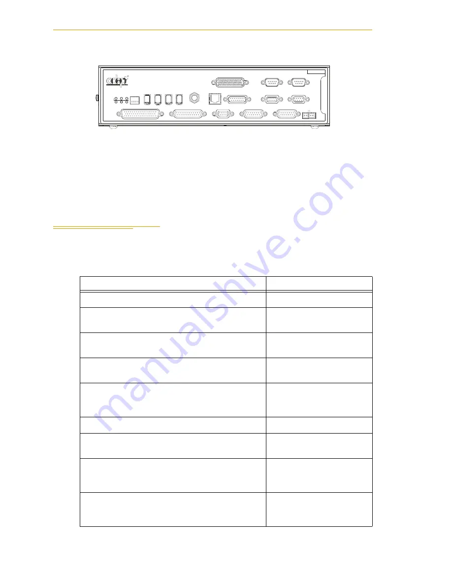
Figure 1-4. Adept SmartController CX
sDIO Module
The optional sDIO module provides 32 optical isolated digital inputs and 32 optical
isolated outputs and also includes an IEEE 1394 interface.
1.2
Installation Overview
The system installation process is summarized in the following table. Refer also to the
system cable diagram in
Table 1-1. Installation Overview
Task to be Performed
Reference Location
1. Mount the robot to a flat, secure mounting surface.
See
.
2. Install the SmartController, Front Panel, pendant
(optional), and AdeptWindows user interface.
See
.
3. Install the IEEE 1394 and XSYS cables between
the robot and SmartController.
See
4. Create a 24 VDC cable and connect it between the
robot and the user-supplied 24 VDC power supply.
See
5. Create a 200-240 VAC cable and connect it
between the robot and the facility AC power
source.
See
6. Install user-supplied safety barriers in the workcell.
See
7. Read
to learn about connecting digital
I/O through the XIO connector on the robot.
See
8. Read
to learn about commissioning the
system, including system start-up and testing
operation.
See
9. Read
if you need to install optional
equipment, including end-effectors, user air and
electrical lines, external equipment, solenoids, etc.
See
R
ON
SmartServo
IEEE-1394
1 2 3 4
SF
ES
HD
SW1
1.1
1.2
2.1
2.2
OK
1
2
3
XDIO
LAN
HPE
OFF
XSYS
CAMERA
Eth 10/100
XUSR
Device Net
XFP
RS-232/TERM
RS-232-1
XMCP
BELT ENCODER
Smar
tController CX
-+
-+
RS-422/485
XDC1 XDC2
24V
5A
*S/N 3562-XXXXX*
RS-232-2


