background image


Calculate the internal dimensions (skirting board to skirting board) of your room and deduct 2cm 

from these. Using these amended dimensions sketch out a diagram of your room and calculate the 

total area that you have. Indicate all dimensions required to determine the available floor area and 

the position of the Thermostat. We would recommend spending ten minutes sketching this out as it 

can save you a lot of time during the installation process if you have a plan. 

        Important


Adept  recommends  that  the  installation  is  documented  with  photos  to  note  the  location  of 

connections and the sensor.


Step 2:


PREPARE SUBFLOOR SURFACE   

The  Foil  heater  must  not  be  installed  in  thinset  cement,  or  in  direct  contact  with  a  cement  or 

concrete  sub-floor.  There  must  always  be  a  soft  insulation  /  underlay  beneath  the  aluminum 

heating  mat/carefully  inspect  the  subfloor  and 

make  sure  it  is  clean,  free  of  sharp      edges, 

protruding  nails  and  any  other  materials  that 

may  damage  the  heating  mat.  Clean  and 

vacuum  the  floor  thoroughly  and  remove  dust 

and debris from the floor that may damage the 

heating  cable.  Ensure  that  the  subfloor  is 

secure and stable. Carefully fill in all cracks. 

Step 3:


LAY THE INSULATION BOARD   

Use  XPS  insulation  board  directly  underneath  the  heating  mat/s,  install  the  boards  in  a  brick 

pattern below and tape the edges to prevent movement of the underlay during installation. 

Step 4: TRANSFER LAYOUT TO FLOOR 

Draw an outline of the layout on the room floor including a foot print of all furnishings that are 

not yet installed. Unroll the first few feet of the Foil Heating Mat. The starting point of the cable 

must be placed within 2.5m from the thermostat. 

        Important


Mark  the  position  of  the  connection  point  between  the  power  lead  and  the  Foil  Heating  Mat 

heating cable. When using a floor temperature sensing thermostat, mark the sensor position in the 

middle of    heating  cables, about 25cm away from the wall  (within the heated area), as close  as 

possible to the thermostat. 


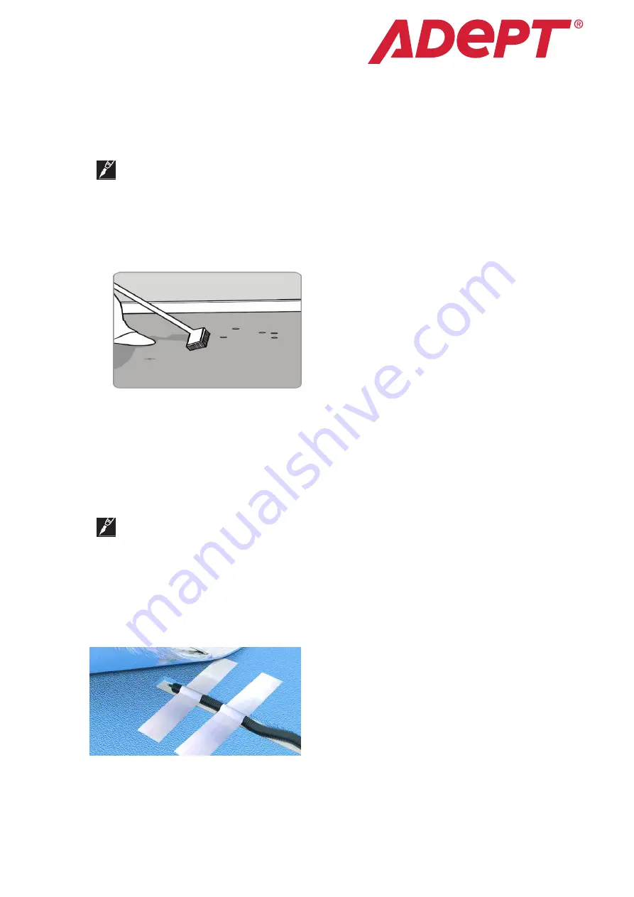
Step 5: INSTALL SENSOR 

If  using  a  floor  temperature  sensing  thermostat, 

install  the  sensor  now,  either  in  conduit  tube,  or 

directly to the subfloor. It is recommended that the 

sensor be installed in conduit tube. This will allow 

the  sensor  to  be  easily  replaced  in  the  unlikely 

event of failure.   

The  tube  needs  to  be  installed  between  the 

thermostat wall box and the sensor position. The conduit tube must be partially countersunk into 

the insulation board.


Run the probe wire down inside the conduit until it just appears from the end 

of the conduit. Cut a channel in the floor and wall up to the thermostat for the sensor conduit. The 

Summary of Contents for HM140/1

Page 1: ...I Foil Heating Mat System Installation Manual Floor heating System...

Page 2: ...ystem 2 2 1 Foil Heating Mat Specifications 2 2 2 Foil Heating Mat typical installations and applications 2 3 Floor Heating Design and Product Selection 3 3 1 Design the Installation 3 3 2 Confirm You...

Page 3: ...l Information 1 1 Use of the Manual Installing Foil Heating Mat is very easy to do Foil Heating Mat Systems combine the highest comfort levels with maximum energy efficiency It s a proven technology t...

Page 4: ...and after installation of wood floor 1 4 Lifetime Warranty From the date of purchase Adept warrants that the Foil Heating Mat heating cable is free from defects in material design and workmanship The...

Page 5: ...showers toilets vanities or cabinets Measure the heated area of the floor For example in Figure 3 the area of the bathroom is 8 75 m2 When you subtract the area of the vanity shower and toilet the to...

Page 6: ...your Foil Heating Mat is no larger than the heated area Following the example from Figure 3 if the heated area is 6 45 m2 select the 6 0 m2 Foil Heating Mat system Figure 3 Heated area example Figure...

Page 7: ...0 96 9 0 5 18 20 59 1 1260 5 48 42 0 HM140 10 10 107 6 0 5 20 20 66 6 1400 6 09 37 8 HM140 12 12 129 2 0 5 24 20 78 8 1680 7 30 31 5 4 Installation Important Tools and materials required You will req...

Page 8: ...PS insulation board directly underneath the heating mat s install the boards in a brick pattern below and tape the edges to prevent movement of the underlay during installation Step 4 TRANSFER LAYOUT...

Page 9: ...e your Foil Heating Mat from the packaging box carry out a resistance test Use a digital ohm meter to measure the resistance of the Foil Heating Mat and compare it to Table Record the measured resista...

Page 10: ...stalling the flooring NEVER CUT THE HEATING CABLE Step 8 STICK THE CONNECTING TAPE In order to protect the mat from damage we need some necessary protective measures A roll of Aluminum tape and Alumin...

Page 11: ...king warmth should be noticeable on the surface of the heating mat within minutes You are now ready to lay the final floor finish Take care not to damage the heating mats Do not drive nails or screws...

Page 12: ...ng on the type of room and your personal preferences 5 Commissioning Important For the extended Lifetime warranty to apply you must perform these tests record the results on the warranty card and reta...

Page 13: ...ed to verify the sensor integrity 1 Set your multimeter to the 200K ohm range 2 Connect the multimeter leads to the red and green lead wires 3 Make sure the meter reads between 9 25K ohms If you get a...

Page 14: ...the Product Selection Table of this manual Refer to Thermostat Installation and Operation Manual Refer to Section 4 of this manual and the Thermostat Installation and Operation Manual Refer to Thermos...

Page 15: ...S ANY WARRANTY EXPRESS OR IMPLIED OF MERCHANTABILITY OR FITNESS FOR A PARTICULAR PURPOSE ADEPT NEITHER ASSUMES NOR AUTHORIZES ANY OTHER PERSON FIRM OR CORPORATION TO ASSUME FOR IT ANY OTHER LIABILITY...

Reviews: