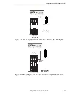
Connecting Output Signals
Adept IO Blox User’s Guide, Rev B
33
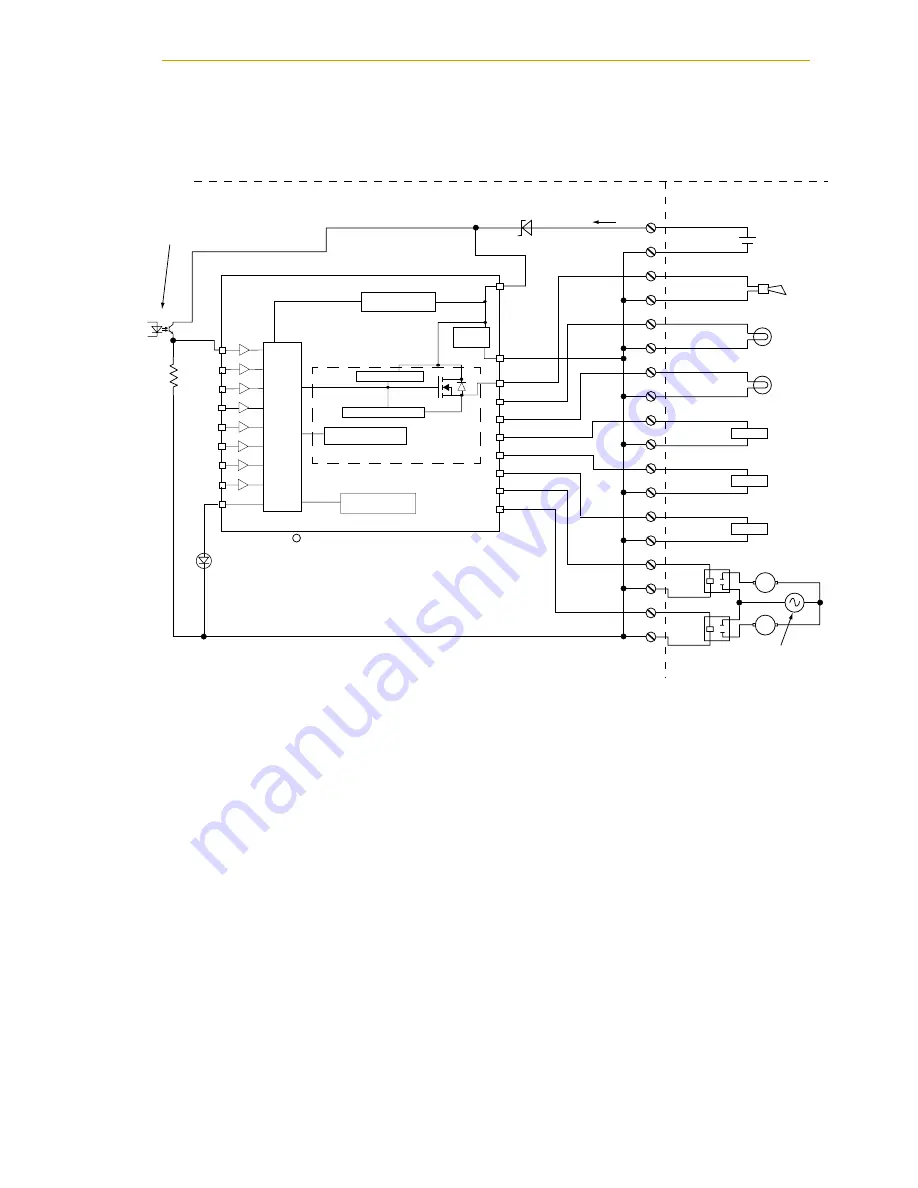
Example Output Schematic
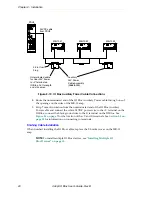
Figure 3-4. Typical User Wiring for Output Signals
UNDERVOLTAGE
DETECTION
ST VN808 or equivalent
V
CC
GND
OUTPUT 1
OUTPUT 2
OUTPUT 3
OUTPUT 4
OUTPUT 5
OUTPUT 6
OUTPUT 7
OUTPUT 8
V
CC
CLAMP
CLAMP POWER
CURRENT LIMITER
JUNCTION TEMP.
DETCTION
CASE TEMP.
DETCTION
Same structure for all
channels
LO
G
IC
I 1
DO_1
10K
Typical Isolated
Output Control
(1 of 8)
Typical User
Supply and Loads
I 2
I 3
I 4
I 5
I 6
I 7
I 8
Status
OVRTMP LED
STMicroelectronics
+V
I
in
+
+
+
User 24VDC
Power Supply
Alarm
Lamp
Lamp
G
O1
O2
O3
O4
O5
O6
O7
O8
G
G
G
G
G
G
G
G
Load
+
Load
Load
M
User AC
Power
Supply
AC Motors
M
L
N
–
–
–
–
+
–
Adept-Supplied Equipment
User-Supplied Equipment
c


