Chapter 3 - Installation for Adept Viper and Cobra s850 Robots
34
Adept PA-4 Power Chassis User’s Guide, Rev E
3.4
PA-4 Connectors
The connectors on the PA-4 EMC box are described below.
Arm Power/Signal Connector
The circular Arm Power/Signal connector on the PA-4 shipped with Viper s650/s850,
Viper s1300, and Cobra s850 systems carries all the motor power and encoder feedback
connections between the controller and the robot. See
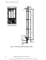
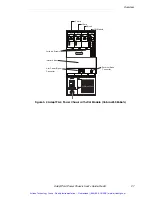
Figure 3-1 on page 26
and
Figure
3-3 on page 28
.
Power and Encoder Connectors
The two rectangular connections on the Viper s1700 serve the same purpose as the Arm
Power/Signal connector on the PA-4 shipped with Viper s650/s850 and Viper s1300
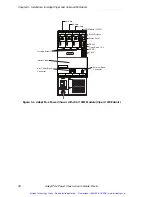
systems. See
Figure 3-4 on page 29
. However, the Viper s1700 uses two cables. The Power
connector carries motor power connections and the Encoder connector carries encoder
feedback connections.
External Brake Connector
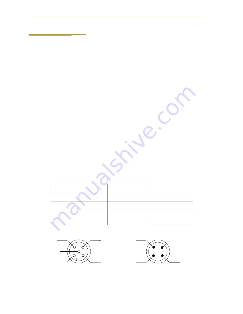
The External Brake connector’s wire list and pinouts are shown below. See
Figure 3-1 on
page 26
for the connector’s location.
This connector provides a low-side driver output that is suitable for driving a 24 V device,
such as a solenoid or pneumatic valve. This driver is internally activated in response to a
J1 brake release command. The solenoid or valve should be connected between pin 1 (24 V
source) and pin 2 (switched GND return). This output is capable of driving up to 10 W
(400 mA @ 24 V). Pins 3 and 4 are reserved for future functionality.
Figure 3-7. External Brake Connector Pinouts
Table 3-3. External Brake Connector Wire List
Pin #
Wire Color
S
ignal
Circ 2 - pin 1
brown
+24
V
DC
Circ 2 - pin 2
white
EXT Brake
Circ 2 - pin 3
blue
+24
V
DC
Circ 2 - pin 4
black
EXT Lamp
Matin
g
Connector -
Supplied
External Brake Connector
on Interface Box (sockets)
4
3
1
2
3
not
connected
2
4
1
Artisan Technology Group - Quality Instrumentation ... Guaranteed | (888) 88-SOURCE | www.artisantg.com

