background image

ARF169 Radio Modems - User guide version V1.4

23

Page

of 40

The ARF169 modem converts data from a serial link into a radio frame for transmission to similar equipment.

 ARF169 radio modems are mainly dedicated to point to point and multipoint communications. They use the harmonised European 169.40625-
169.44375MHz, band that is usable without a licence. Their excellent sensitivity coupled with power up to 500mW enable data transmissions 
up to 15km to be achieved.

The169MHz frequency band allows the use of : 
•  5 communication channels at 2.4kbps :
•  3 communication channels at 9.6kbps
•  1 communication channel at 38.4kbps

The operating parameters of these modems (serial link, radio management, etc) can be updated by commands on the serial link. 
The use of the dedicated Adeunis software, “Adeunis RF - Stand Alone Configuration Manager”, available from the 

www.adeunis-rf.com

 website 

enables you to commission your ARF169 modems very easily.

1.1.  Modem versions

All products are available in TNC base for remote aerial versions..

Reference

Designation

Power/RF power

ARF7944BA 

ARF169 ULR - TNC. ANTENNA

500mW / 27dBm

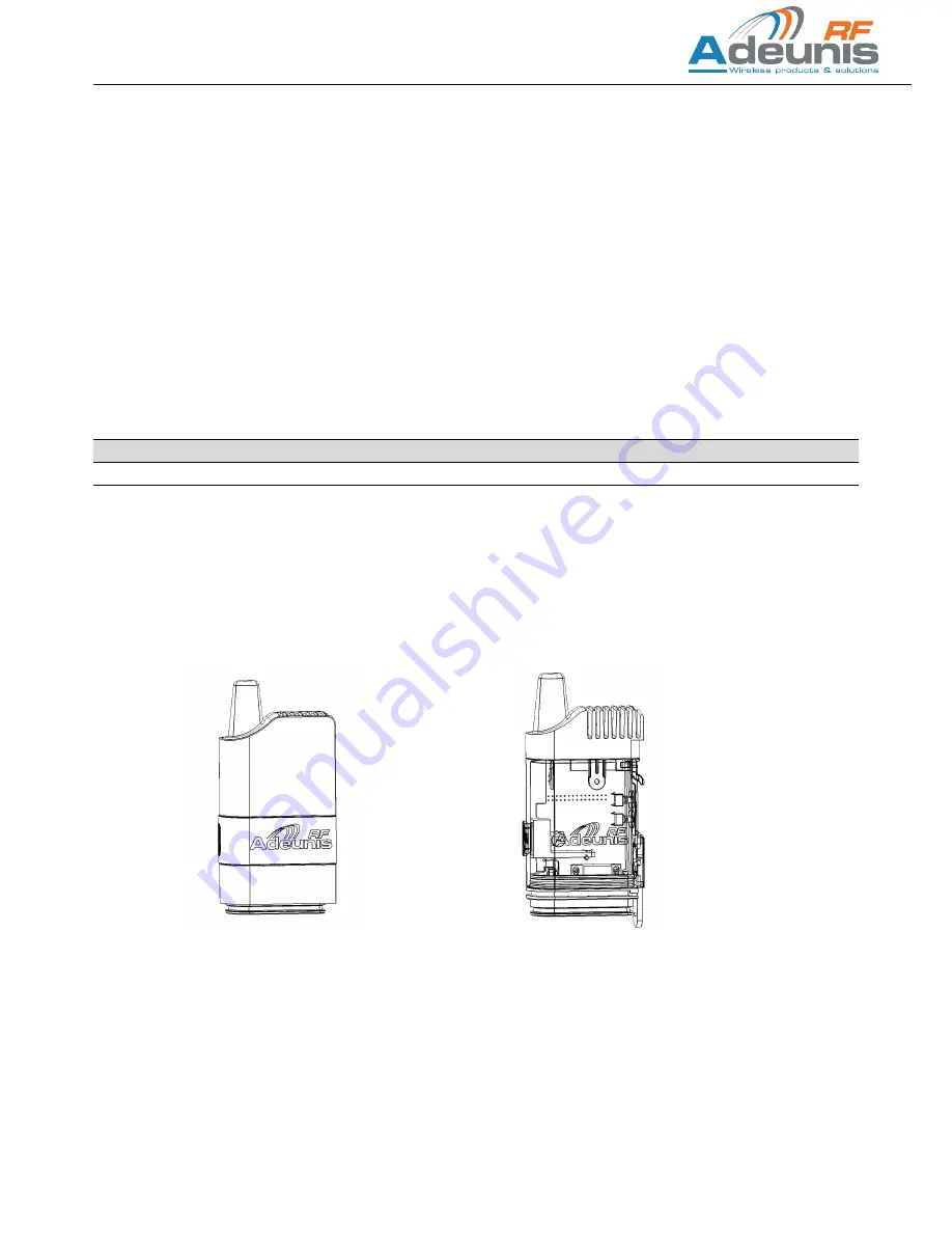
Each of the products listed above is supplied in the “standard” version.

The standard version has a protective casing which can be removed to obtain access to the DIN-Rail attachment.

Standard version 

with protective casing

Standard version 

without protective casing

Summary of Contents for ARF169

Page 1: ...ems Mode d emploi User guide version V1 4 FRANCAIS ENGLISH ADEUNIS RF 283 rue Louis Néel Parc Technologique Pré Roux 38920 CROLLES France Tel 33 0 4 76 92 07 77 Fax 33 0 4 76 04 80 87 www adeunis rf com arf adeunis rf com ...

Page 2: ...Notre site Web contient de nombreuses informations utiles information sur les modules et modems radio guides d utilisation logiciel de confi guration et de documents techniques qui peuvent être accessibles 24 heures sur 24 Our website contains many useful information modules and stand alone products information user guides configuration software and techni cal documents which can be accessed 24 ho...

Page 3: ...rials have been eliminated We have made every possible effort to ensure that the packaging can easily be separated into three types of materials cardboard box expandable polystyrene buffer material and polyethylene bags and protective foam layer Your appliance is composed of materials that can be recycled and reused if it is dismantled by a specialist company Please respect local regulations conce...

Page 4: ...harges 12 2 Caractéristiques électriques et radio 12 2 1 Valeurs maximales 12 2 2 Spécification générales 12 2 3 Caractéristiques radio 13 2 3 1 Introduction aux exigences radio 13 2 3 2 Duty Cycle 13 2 3 3 Mode de fonctionnement des modems ARF169 13 2 3 4 Mode standard 13 3 Echange de données Mode de Communication 14 3 1 Protocole asynchrone paquetisé 14 3 1 1 Description du protocole 14 3 1 2 Mo...

Page 5: ...29 2 3 Radio specifications 30 2 3 1 Introduction to the radio requirements 30 2 3 2 Duty Cycle 30 2 3 3 ARF169 modem operating mode 30 2 3 4 Standard mode 30 3 Data exchange Communication mode 31 3 1 Packet protocol 31 3 1 1 Protocol description 31 3 1 2 Non secured Packet Protocol 31 3 1 3 Secured Packet protocol 31 3 1 4 Transmission integrity control 31 3 1 5 Implementation 31 3 1 6 Transmissi...

Page 6: ...ation à 9 6kbps 1 canal de communication à 38 4kbps Les paramètres opératoires de ces modems lien série gestion radio peuvent être mis à jour par des commandes sur le lien série L utilisation du logiciel Adeunis dédié Adeunis RF Stand Alone Configuration Manager disponible sur le site www adeunis rf com vous permettra de mettre en œuvre très simplement vos modems ARF169 1 1 Versions de modems Le m...

Page 7: ...vent être montées sur les modems ARF169 de sorte à autoriser leur utilisation en environements difficiles Option IP53 avec ajout d un capot de protection des raccordements électriques par un système de mousse compensée Option IP67 avec ajout d un capot de protection des raccordements électriques par un système de presse étoupe BP 1 BP 2 Verrou Rail DIN SubD9 RS232 RS485 Jack alimentation Enveloppe...

Page 8: ...insérés dans le capot par la partie inférieure puis connectés sur les embases femelles du modem voir partie raccordement électrique La partie supérieure du capot est ensuite insérée sur la platine inférieure modem supportant les connecteurs femelles et qui aura été préalablement équipée du joint torique C est l enveloppe de protection en U du modem qui viendra finalement assurer le maintien du cap...

Page 9: ...ion continue comprise en 4 5V mini et 36V maxi Le système intègre une protection contre l inversion de polarité 1 6 2 Affectation du connecteur data série SubD9 N de broche SubD9 modem RS232 SubD9 modem RS485 2 1 2 RXD Modem Data Out TXD RXD B 3 TXD Modem Data In TXD RXD A 4 5 GND 6 Sel RS232 7 RTS 1 8 CTS 1 9 Not used 1 RTS CTS ne sont utiles que si l on utilise le contrôle de flux RS232 Voir 4 C...

Page 10: ... de liaison série AUTO BP1 appui court sur BP1 inférieur à 3 secondes Un appui court sur PB1 3s permet la restitution des paramètres de liaison série par défaut Auto détection d interface Autobaud data 8 bits pas de parité pas de contrôle de flux Cette action sera confirmée par 3 cligno tements du voyant vert Entrée en mode com mande BP2 et BP1 1 appuyer sur BP2 et maintenir 2 appuyer sur BP1 et m...

Page 11: ... armoire électrique l antenne doit être installée en extérieur Il en est de même si le modem est placé à l intérieur d un bâtiment et qu il doit communiquer avec un modem positionné en extérieur Le câble coaxial doit être le plus court possible pour information câble de 25m 6db d atténuation portée divisée par 2 20cm 200cm Antenne 100cm Antenne 100cm 1 9 4 Positionnement des câbles alimentation et...

Page 12: ...le d installation de parafoudre N Désignation Référence 1 Connecteur TNC du modem ARF169 2 Ecrou de Montage Fourni avec le parafoudre 3 Rondelle Eventail Fourni avec le parafoudre 4 Fil 12 10 AWG Doit être connecté à la terre 5 Cosse Ronde RS 613 9429 6 Joint torique Fourni avec le parafoudre 7 Parafoudre RS 111 658 8 Adaptateur TNC Male Male RS 193 7953 9 Antenne 2 Caractéristiques électriques et...

Page 13: ...te permanente de l interface RF et du port UART Dès qu une trame est démodulée en provenance de la liaison RF son contenu est transmit sur le port UART Dès qu une chaîne de caractères est détectée sur le port UART elle est transmise sur la liaison RF A la 1ère mise sous tension les paramètres sont les paramètres par défaut ou réglages usine Lors des mises sous tensions suivantes les paramètres uti...

Page 14: ... le champ type de paquet Le FIFO entrant peut accumuler jusqu à 1024 octet de données Aucune autre donnée ne doit être transmise dans le FIFO tant qu un bloc de données de 1024 octets n a pas été libéré par le radio Pour empêcher le dépassement de la FIFO le contrôle de flux du matériel peut être activé Dans ce cas le signal RTS sera réglé lorsque le FIFO d entrée est presque plein pour empêcher l...

Page 15: ...radio s effectue à travers le registre S254 cf 5 3 Les notions d adressage communication en broadcast communication dans un groupe et communication adressée entre produits sont dispo nibles et décrites ci dessous 3 2 3 Adressage Le produit dispose de différents modes d adressage configurables à travers les registres produits Les modes suivants sont disponibles Mode transparent sans sous réseau Mod...

Page 16: ...nde Commande Description Réponse U majuscule Autorise la détection automatique du débit UART voir note 1 Retourne les paramètres de la liaison série RS232 ou RS485 et débit Note A cette sollicitation le modem répondra par la configuration qu il a détecté Type de Liaison Débit UART Exemple RS232 9600 Si le modem ne répond pas ou répond par une autre chaîne de caractères à la demande de synchronisat...

Page 17: ...C0 087 096 101dBm cr lf Soit dans l ordre RSSI mini RSSI moyen RSSI maxi mesurés sur cette période 4 5 Test d émission réception Cette fonction permet la mise en œuvre rapide d une communication sur le terrain pour vérifier la limite de portée entre les deux modems avec les choix définitifs de fréquence débit puissance Les commandes ATT00 et ATT01 permettent d établir une communication entre deux ...

Page 18: ...s registres Commande Description Réponse Autorise l entrée en mode commande CM pour confirmer l entrée dans le mode commande ATO Sortie du mode commande O si l opération est acceptée E si l opération est refusée 5 2 Commandes AT Une commande débute avec les 2 caractères ASCII AT suivis d un ou plusieurs caractères et données voir ci après la syntaxe des com mandes AT disponibles sur le modem Chaqu...

Page 19: ...0 Demande de sélection de la puissance RF à 27dBm O ATS200 Retourne la valeur du registre S200 S200 4 ATS231 Retourne la valeur du registre S231 S231 0 AT W Demande de mémorisation de l état des registres W le canal choisi n est pas disponible au débit RF 9 6kbps La sauvegarde ne sera pas effectuée ATO Demande de sortie du mode commande W le canal choisi n est pas disponible au débit RF 9 6kbps La...

Page 20: ... mode commande par l UART 43 Le code d entrée est 3 fois le caractère Exemple si le caractère programmé en S214 est le code ASCII de soit 43 La valeur peut être comprise entre 1 et 255 S215 Interface UART 0 Position des switch internes 1 RS232 2 RS485 mode no Term 3 RS485 mode Term 4 Auto 1 Sauf demande particulière la position des switch internes sur modem ARF169 est mode Auto idem S215 4 Voir no...

Page 21: ...liaison série le caractère U voir 4 1 Commande d auto détection Après la bonne exécution de la commande d auto détection une lecture du registre S210 ATS210 retournera la valeur de débit UART identi fiée dans la table valeur 3 à 7 Elle sera mémorisée sur reconnaissance de la commande AT W Note2 Sauf autre demande particulière les switchs internes au modem réglages usine sont basculés sur le mode A...

Page 22: ...avant que les données en mémoire tampon aient atteint le seuil du registre S218 c est un déclenchement au temps A noter que la programmation à 0 du registre S217 pas de timeout implique forcément que le seuil du registre S218 soit atteint pour démarrer la transmission Exemple 6 Historique de document Version de mode d emploi Contenu V1 4 Regsitre S243 V1 3 Modification valeur de duty cycle V1 2 Mo...

Page 23: ...1 communication channel at 38 4kbps The operating parameters of these modems serial link radio management etc can be updated by commands on the serial link The use of the dedicated Adeunis software Adeunis RF Stand Alone Configuration Manager available from the www adeunis rf com website enables you to commission your ARF169 modems very easily 1 1 Modem versions All products are available in TNC b...

Page 24: ...le and can be fitted to ARF868 modems to enable them to be used in difficult environments IP53 option with the addition of a protective casing for the electrical connections by a system of compensated foam IP67 option with the addition of a protective cover for the electrical connections by a system of cable glands BP 1 BP 2 DIN Rail lock SubD9 RS232 RS485 Supply jack U shaped protective casing TN...

Page 25: ...d connected to the female bases on the modem see electrical connection part The top part of the cover is then inserted onto the bottom plate of the modem holding the female connectors which has previously been fitted with an O ring seal It is the U shaped modem shield that finally holds the IP53 casing once it is in place It then only remains to close the IP53 casing onto the bottom by the followi...

Page 26: ... between 4 5V min and 36V max The system includes a device against polarity reversal 1 6 2 Functions of the SubD9 serial data connector Pin no SubD9 Modem RS232 SubD9 Modem RS485 2 1 2 RXD Modem Data Out TXD RXD B 3 TXD Modem Data In TXD RXD A 4 5 GND 6 Sel RS232 7 RTS 1 8 CTS 1 9 Not used 1 RTS CTS are only used if the RS232 data rate control is used See 4 Configuration 2 Half duplex connection o...

Page 27: ...he AUTO serial link parame ters BP1 Brief pressure on BP1 inferior to 3 seconds Brief pressure on PB1 3s enables restoration of the serial link default settings interface self detection Auto baud 8 bit data no parity no data rate control This action will be confirmed by 3 flashes of the green indicator light Entry into the Command mode BP2 and BP1 1 Press BP2 and hold 2 Press BP1 and hold Holding ...

Page 28: ...ch other If the modem is installed in an electrical cabinet the aerial should be installed outside The same applies if the modem is placed inside a building and it needs to communicate with a modem positioned outside The co axial cable should be as short as possible memo cable of 25m 6db of attenuation range divided by 2 20cm 200cm Antenne 100cm Antenne 100cm 1 9 4 Positioning of power and serial ...

Page 29: ...ning arrester installation No Description Reference 1 TNC connector of ARF868 modem 2 Mounting nut delivered with product 3 Tooth lock washer delivered with product 4 12 10 AWG wire must be earthed 5 Round terminal RS 613 9429 6 O ring seal delivered with product 7 Lightning arrestor RS 111 658 8 Male Male TNC adapter RS 193 7953 9 Aerial 2 Electrical and radio specifications 2 1 Maximum values Pa...

Page 30: ... listening mode of the RF interface and the UART port As soon as a frame from the RF link is demodulated its content is transmitted to the UART port As soon as a character chain is detected on the UART port it is transmitted to the RF link On first switching on the parameters are the default parameters or factory settings At subsequent switchings on the parameters used are those last memorised wit...

Page 31: ...data has to be set in the fifo while a 1024 bytes block of data has not been released by the radio transmission layer To prevent from input fifo overrun the hardware flow control may be activated In this case the RTS signal will be set when the incoming fifo is almost full to prevent the host controller from sending new data 3 1 2 Non secured Packet Protocol In non secured mode each packet is tran...

Page 32: ...ribed below 3 2 3 Addressing The product has various addressing modes that are configurable via the product registers The following modes are available Transparent mode without sub network Transparent mode with sub network Addressed mode without sub network Addressed mode with sub network The transparent modes are intended for inter product communication all products are recipients of the frames t...
Page 33: ...equest the modem will reply by the configuration that it has detected type of link UART data rate E g RS232 9600 If the modem does not reply or replies by another character chain to the synchronisation request U a new test can be attempted after having disconnected and reconnected the electricity supply to the appliance If these attempts produced no effect check that the serial link of the moni to...

Page 34: ...in RSSI mean RSSI max measured over this period 4 5 Transmission reception test This function enables a communication to be put into operation quickly in the field to check the range limit between two modems with the defined choices of frequency data rate power etc The ATT00 and ATT01 commands enable communication to be established between two modems with a minimum of material constraints Sending ...

Page 35: ...CM to confirm entry in command mode ATO Exit command mode O cr if operation OK E cr if error 5 2 AT Commandes A command starts with the two ASCII characters AT followed by one or more characters and data see C below for the syntax of AT com mands available on the modem Each command should end with a CR or CR LF the two possibilities are accepted CR signifies Carriage Return LF signifies Line Feed ...

Page 36: ...at 9 6kbps O ATS200 9 Request for channel selection 9 E invalid channel ATS200 527 Request for channel selection 527 O ATS231 0 Request for RF power at 27dBm O ATS200 Returns S200 register value S200 527 ATS231 Returns S231 register value S231 0 AT W Storage request of the registers status W the selected channel is not available at 9 6kbps RF data rate The value storage will not be performed ATO R...

Page 37: ...211 UART data lenght 0 7 Bits 1 8 Bits 1 S212 UART parity 0 No parity 1 Parity 2 Odd parity 0 S214 Input character in command mode ASCII code except 0 0 Disabling entry into command mode by UART 43 The input code is 3 times the character Example if the character programmed in S214 is the ASCII code of wether 43 Value between 1 and 255 S215 UART interface 0 Internal switches positions 1 RS232 2 RS4...

Page 38: ...to the speed of the serial link provided it is configured in 8 bits 1 stop bit no parity To trigger this procedure the monitoring equipment must transmit on the serial link the character U see 4 1 self detection command After correct execution of the self detection command reading register S210 ATS210 will return the UART data rate value identified in the table value 3 to 7 It will be memorised on...

Page 39: ...ata On the other hand when the timeout of register S217 expires before the data in the buffer memory reach the threshold of register S218 it is triggering on time It should be noted that programming register S217 to 0 no timeout means that the S218 register threshold must be reached to start transmis sion Below example of S217 S218 register usage TX RF via S218 S217 10 millisecondes S218 3 octets ...

Page 40: ...11 65 UE Erp 2009 125 The following standards and or other normative documents have been used to demonstrate the conformity to the above directives EN300220 1 2V2 4 1 EN60950 1 2006 A11 2009 A1 2010 A12 2011 EN301489 1V1 9 2 EN301489 3V1 4 1 EN62311 2008 EN50581 2012 EN50563 EN50564 Notes Conformity has been evaluated according to the procedure described in Annex IV of the RTTE Directive Statement...

Reviews: