DTU4x0 GPRS/NB-IoT Data Loggers
User Guide. r. 2.01 | 2022-05-17
Tel.: +420 234 076 670
19
e-mail: info@adgt.cz
4.
Connect
meters and sensors to P1-P11 contacts of the data logger
Wiring diagrams are presented in
DTU4x0 Interfaces and Wiring Diagrams
For pinouts see
DTU4x0 terminal block contacts
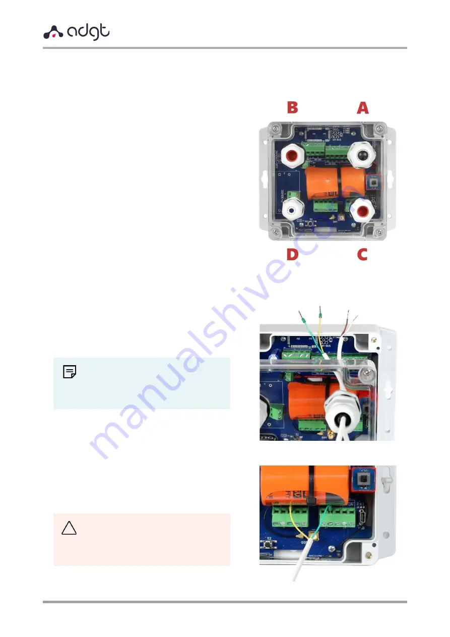
There are four cable glands on the case cover:
−
A
–
the main
,
for meters and sensors
−
B
–
additional
,
for meters and sensors
−
C
– for an external antenna cable
−
D
– for an external power cable.
The hole of cable gland
A
is closed with a
rubber plug. To insert cables into the plug, you
need to make an incision of the desired size.
The holes of cable glands
B
and
C
are closed
with blind plugs. To use these outlets, the plugs
should be removed and the cables sealed with
the self-adhesive insulation tape (included).
a)
Slightly unscrew the swivel nut of the
cable gland and lead the cable inputs of
measuring devices through.
NOTE:
We recommend crimping the stranded
wires of the meters with wire ferrules
before connecting.
b)
Insert wires into the corresponding
terminal connectors and tighten the
screws to fix the wires.
CAUTION!
−
P1-P11
– contacts “–”
−
3.6V
– contacts “+”


