GB
GB
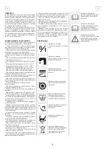
ATTENTION:
For the daily recharge of the batteries it is necessary
to follow strictly all the indications given by the
manufacturer/distributor. All the installation and
maintenance operations must be carried out by
qualified staff.
Danger of gas exhalations. Fire
danger: do not approach with free flames.
BATTERIES DISPOSAL
It is compulsory to hand over exhaust batteries, clas-
sified as dangerous waste, to an authorized institu-
tion according to the current laws.
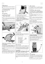
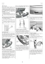
BATTERIES CHARGE LEVEL INDICATOR
The charge level of the batteries is visible by switch-
ing on the machine with the general switch (1).
green led on = batteries charged.
green led blinking = batteries almost discharged.
red led on = complete discharge of the batteries
with consequent automatic switching off of all the
functions (immediate recharge necessary).
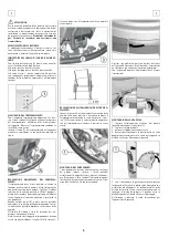
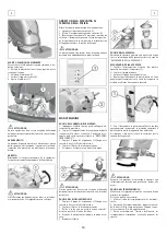
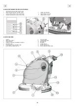
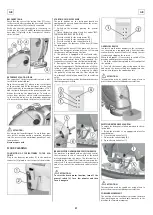
SQUEEGEE ASSEMBLY
With the squeegee support lowered, slide the two
stud bolts (A) placed on the upper part of the squee-
gee, inside the slots on the support. Block the squee-
gee by rotating the lever (B) clockwise.
Insert the squeegee hose (C) into its coupling, re-
specting its position as indicated in the figure.
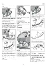
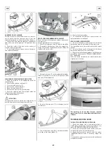
ADJUSTMENT OF THE SQUEEGEE HEIGHT
The squeegee must be adjusted in height depending
on the rubber wear. In order to guarantee a perfect
drying during the operation, the lower blade of the
rear squeegee rubber (D) must work slightly bent
backwards (operator side) in uniformed way in all its
length.
Acting clockwise upon the two registers (E) it is pos-
sible to increase the bending of the rubber. Acting
counterclockwise it is possible to decrease the rubber
bending.
The label (G) indicates the rotation sense to increase
or reduce the height.
Note: The wheels of the squeegee support must be
adjusted through the registers (E) at the same height
so that the squeegee works parallel to the floor.
ADJUSTMENT OF THE SQUEEGEE INCLINATION
In case of need, to increase the rubber bending in
the central part, it is necessary to tilt the squeegee
body rotating counterclockwise the register (F). To
increase the rubber bending on the squeegee ex-
tremities, rotate the register clockwise.
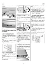
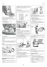
SPLASH GUARD ASSEMBLY
The two splash guards have to be assembled onto the
brush base group. Insert the metal strips inside the
suitable slots present on the rubber. Place the round
hole at the flat extremity of the strip onto the screw
placed in the front part of the brush base group. Se-
cure the strips through the nut blocking it.
Screw down the knobs in the rear part of the cover
in the free extremity of the metal strips. The opera-
tion has to be carried out for both splash guards.
With the brush assembled, the splash guard must
slightly touch the floor.
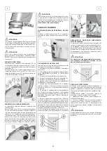
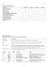
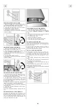
BRUSH ASSEMBLY
1. Take off the electric supply to the brush motor
unplugging the connector (1).
2. Take off the squeegee.
3. Lift the support raising the lever.
4. Rotate backwards the machine until it rests on
the support wheels, so to lift the brush base.
5. With the brush base group in lifted position, in-
sert the brush into its plate seat underneath the
brush base turning it until the three metal buttons
are properly seated in their slots; rotate energically
the brush to push the button towards the coupling
spring until it gets blocked.
The figure shows the rotating sense for the brush
coupling.
ATTENTION:
The handling of the brushes operation must be car-
ried out using suitable gloves to protect both me-
chanically from contact with the bristles and the
chemical risk of contact with dangerous solutions.
ATTENTION:
Use only the brush supplied with the machine or the
ones indicated in the paragraph “RECOMMENDED
BRUSHES”. The use of other brushes can compromise
security.
20
Summary of Contents for 48803020
Page 2: ......
Page 14: ...I I 14...
Page 26: ...GB GB 26...
Page 38: ...F F 38...
Page 50: ...D D 50...

