


GB
GB
9
ATTENTION:
This operation must be carried out using gloves to
protect from contact with dangerous solutions.
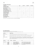
5. Open the bar of the right side rubber after hav-
ing released it pulling the stop (1) upwards.
6. Take off the stop (2) then unscrew and take off
the knob so to open the blocking support as shown
in the figure.
7. Extract the support plates (3) and (4) of the
brushes pulling them outwards by holding their han-
dles.
8. Extract the rear brush (5) and the front brush (6).
9. When reassembling the rear brush (5) pay atten-
tion to the bristles design, so that it will be assem-
bled always in the same direction as shown in the
figure.
10. During the reassembly of the brush (6), insert it
into the brush base from the part where the seat is
deeper (about 40mm). The opposite part with a
depth of about 13,5mm has to look towards the
support plate.
11. Place the support plates (3) and (4) into their po-
sition, then the blocking support, screw down the
knob and insert once more the stop (2) and finally
re-position and block the bar of the side rubber
through the stop (1).
ATTENTION:
The brushes must be inserted easily without using
tools in order not to damage or force them.
Use only brushes supplied with the machine or the
ones indicated in the paragraph “RECOMMENDED
BRUSHES”. The use of other brushes can compromise
the good washing result.
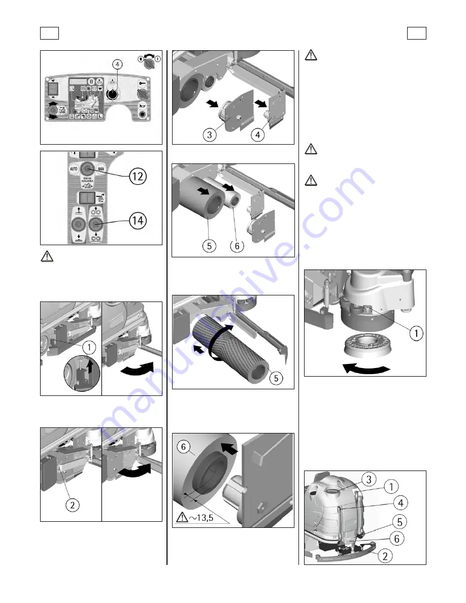
SIDE BRUSH ASSEMBLY AND DISASSEMBLY
The machine is equipped with a side brush that per-
mits to clean near the right side borders.
To assemble the brush, the device has to be in rest
position at machine stop.
ATTENTION:
To carry out brushes assembly operations with the
electric supply on, may cause damages to hands.
ATTENTION:
This operation must be carried out using gloves to
protect from contact with dangerous solutions.
1. Keep the push button (1) pressed that blocks the
rotation of the brush plate.
2. Insert the brush into its plate seat underneath
the brush base turning it until the three metal but-
tons are properly seated in their slots; rotate
energically the brush to push the button towards the
coupling spring until it gets blocked.
The figure shows the rotating sense for the brush
coupling. For its release, rotate the other way round.
FLOOR CLEANING
RECOVERY TANK
Verify that the squeegee hose couplings (1/2) are
correctly inserted into their seats and that the ex-
haust hose plug (4) placed in the rear part of the
machine is well closed.
Check that the inspection cap (3) placed on the up-
per part of the tank is well closed.
Finally, verify the correct tightening of the closing
lever (5) of the cleaning door (6) placed in the lower
part of the tank.


