background image


4

Installation

Installing the FCR200  . . . . . . . . . . . . . . . . . . . . . . . . . . . . . . . . . . . . . . . . . . . . . . . . . . . . . 4-3

Location   . . . . . . . . . . . . . . . . . . . . . . . . . . . . . . . . . . . . . . . . . . . . . . . . . . . . . . . . . . . . . . . . 4-3

Unpacking the Box   . . . . . . . . . . . . . . . . . . . . . . . . . . . . . . . . . . . . . . . . . . . . . . . . . . . . . . . 4-4

Mounting the FCR200 in a Rack  . . . . . . . . . . . . . . . . . . . . . . . . . . . . . . . . . . . . . . . . . . . . 4-4

Materials Needed:   . . . . . . . . . . . . . . . . . . . . . . . . . . . . . . . . . . . . . . . . . . . . . . . . . . . . 4-4
Required tools:  . . . . . . . . . . . . . . . . . . . . . . . . . . . . . . . . . . . . . . . . . . . . . . . . . . . . . . . 4-5

Installation Procedure . . . . . . . . . . . . . . . . . . . . . . . . . . . . . . . . . . . . . . . . . . . . . . . . . . . . . 4-6

Ear Rail Mounting   . . . . . . . . . . . . . . . . . . . . . . . . . . . . . . . . . . . . . . . . . . . . . . . . . . . . 4-6
Slide Rail Mounting (Optional)  . . . . . . . . . . . . . . . . . . . . . . . . . . . . . . . . . . . . . . . . . 4-8

Interfaces and Connections  . . . . . . . . . . . . . . . . . . . . . . . . . . . . . . . . . . . . . . . . . . . . . . . 4-11

Fibre Channel Connection  . . . . . . . . . . . . . . . . . . . . . . . . . . . . . . . . . . . . . . . . . . . . . . . . 4-12

SCSI Connection   . . . . . . . . . . . . . . . . . . . . . . . . . . . . . . . . . . . . . . . . . . . . . . . . . . . . . . . . 4-15

Ethernet Connection  . . . . . . . . . . . . . . . . . . . . . . . . . . . . . . . . . . . . . . . . . . . . . . . . . . . . . 4-17

Serial Port Connection   . . . . . . . . . . . . . . . . . . . . . . . . . . . . . . . . . . . . . . . . . . . . . . . . . . . 4-18

Autobaud Feature  . . . . . . . . . . . . . . . . . . . . . . . . . . . . . . . . . . . . . . . . . . . . . . . . . . . . . . . 4-19

Connecting the Power Cord   . . . . . . . . . . . . . . . . . . . . . . . . . . . . . . . . . . . . . . . . . . . . . . 4-20

Management Information Base (MIB)   . . . . . . . . . . . . . . . . . . . . . . . . . . . . . . . . . . . . . . 4-21

MIB Fibre Channel Interface Information  . . . . . . . . . . . . . . . . . . . . . . . . . . . . . . . . . . . 4-21

MIB SCSI Interface Information   . . . . . . . . . . . . . . . . . . . . . . . . . . . . . . . . . . . . . . . . . . . 4-21

MIB Ethernet and Serial Interfaces Information  . . . . . . . . . . . . . . . . . . . . . . . . . . . . . . 4-22

Summary of Contents for FCR 200

Page 1: ...FCR 200 Operator Guide ...

Page 2: ...cation may describe designs for which patents are pending or have been granted By publishing this information ADIC Europe conveys no license under any patent or any other right ADIC Europe makes no representation or warranty with respect to the contents of this document and specifically disclaims any implied warranties of merchantability or fitness for any particular purpose Further ADIC Europe re...

Page 3: ...zation 1 3 Associated Documents 1 4 Explanation of Symbols and Notes 1 4 Federal Communication Commission Notice US Only 1 5 IEC Statement Worldwide 1 5 Canadian Notice Avis Canadien 1 5 European Union Notice 1 5 VCCI Statement Japan 1 6 Declaration of Conformity 1 6 ...

Page 4: ...l Dimensions 2 5 Operating Environment 2 5 Non operating Environment 2 5 Power 2 5 FCR200 Benefits 2 6 Point to Point 2 6 Single Initiator 2 6 Multiple Initiators 2 7 How the FCR200 Works 2 8 Operating as Both a SCSI and Fibre Channel Device 2 9 The SCSI Side 2 9 The Fibre Channel Side 2 9 Mapping Devices 2 10 Processing SCSI Information 2 10 Processing Fibre Channel Information 2 11 3 Safety Safe...

Page 5: ...4 3 Location 4 3 Unpacking the Box 4 4 Mounting the FCR200 in a Rack 4 4 Materials Needed 4 4 Required tools 4 5 Installation Procedure 4 6 Ear Rail Mounting 4 6 Slide Rail Mounting Optional 4 8 Interfaces and Connections 4 11 Fibre Channel Connection 4 12 SCSI Connection 4 15 Ethernet Connection 4 17 Serial Port Connection 4 18 Autobaud Feature 4 19 Connecting the Power Cord 4 20 Management Infor...

Page 6: ...ressing 5 4 General SCSI Configuration 5 5 Fibre Channel Host to SCSI Target Configuration 5 5 Address Mapping 5 5 Indexed Addressing 5 6 Auto Addressing 5 7 SCC Addressing 5 8 SCSI Host to Fibre Channel Target Configuration 5 8 6 Configuration Configuring the FCR200 6 3 Operation Indicators 6 4 Host Device Configuration 6 5 Device Management 6 5 Serial 6 5 Ethernet 6 6 SNMP 6 6 Communicating with...

Page 7: ...tion 6 15 Reset Configuration to Factory Defaults 6 16 Display POST Status 6 16 Display Trace and Assertion History 6 17 Reboot 6 17 Download Firmware 6 18 To Download Firmware 6 18 Configuring the FCR200 s Ethernet Port 6 20 SNMP Configuration 6 21 Toggle Trap 6 21 SNMP Configuration with Traps Enabled 6 22 GET and SET Community Names 6 22 IP Address for Traps 6 22 Trap Priority 6 22 7 Troublesho...

Page 8: ...ems 7 7 Contact Customer Support 7 7 A Ethernet Assignments RJ 11 Serial and RJ 45 Ethernet Pin Assignments A 3 B Fibre Channel Interface and Commands Fibre Channel Interface and Commands B 3 Download Command B 3 Report LUNs Command B 5 PRLI Data B 6 C SCSI Interface and Commands SCSI Interface and Commands C 3 SCSI Inquiry Data C 3 ...

Page 9: ...ddressing Structures and Operation Addressing Structures and Operation D 3 SCC Addressing Option D 5 Indexed Addressing Option D 6 Auto Assigned Addressing Option D 7 E Reference Standards Standards E 3 Glossary Index ...

Page 10: ...x Contents 62 9301 01 ...

Page 11: ... Materials Needed 4 4 Figure 4 2 Cage Nut Installation 4 6 Figure 4 3 Mounting at Front of rack 4 7 Figure 4 4 Mounting at back of Rack 4 7 Figure 4 5 Front of Mounting Brackets 4 8 Figure 4 6 Attaching the Brackets 4 9 Figure 4 7 Attaching Brackets 4 9 Figure 4 8 Attaching Side Rails 4 10 Figure 4 9 Port Locations 4 11 Figure 4 10 Configuration with Tape library 4 12 Figure 4 11 Fibre Channel Por...

Page 12: ...gure 4 16 FCR200 Serial Port 4 18 Figure 4 17 FCR200 Power Switch and Outlet 4 20 Figure 5 1 Configuration with tape library 5 3 Figure 6 1 FCR200 LEDs 6 4 Figure A 1 RJ 11 Pin Assignment A 3 Figure A 2 RJ 45 Pin Assignment A 4 ...

Page 13: ...ble B 3 Report LUN Parameter List B 5 Table B 4 FCR200 PRLI Response Data B 6 Table C 1 FCR200 Inquiry Data C 3 Table D 1 SCC Addressing Structure D 3 Table D 2 Peripheral Device Addressing LUN Structure D 3 Table D 3 SCC Logical Unit Addressing LUN Structure D 4 Table D 4 Address Method Definition D 4 Table D 5 Arbitrated Loop Node Number to ALPA Lookup Table D 4 Table D 6 Example of Fibre Channe...

Page 14: ...xiv Tables 62 9301 01 ...

Page 15: ...n 1 3 Associated Documents 1 4 Explanation of Symbols and Notes 1 4 Federal Communication Commission Notice US Only 1 5 IEC Statement Worldwide 1 5 Canadian Notice Avis Canadien 1 5 European Union Notice 1 5 VCCI Statement Japan 1 6 Declaration of Conformity 1 6 ...

Page 16: ...1 2 Introduction 62 9301 01 ...

Page 17: ...ns chapters detailing the operation of the FCR200 The chapters topics include Chapter 1 Introduction Describes the overview intended audience organization associated documents explanation of symbols and notes and how to obtain additional assistance Chapter 2 Description Describes general information about the FCR200 Chapter 3 Safety Describes the hazard symbols messages safety features and operati...

Page 18: ...pendix D Addressing Structures and Operation Describes various addressing schemes for devices Appendix E Reference Standards List applicable standards Glossary Index Associated Documents None Explanation of Symbols and Notes The following symbols and highlighted passages note important information Detailed explanations for the above symbols are provided in Safety Instructions on page 3 3 1 2 Press...

Page 19: ...terference in which case the user will be required to correct the interference at personal expense IEC Statement Worldwide This is a Class A product In a domestic environment this product may cause radio interference in which case the user may be required to take adequate measures Canadian Notice Avis Canadien This Class A digital apparatus meets all requirements of the Canadian Interference Causi...

Page 20: ...1 6 Introduction 62 9301 01 EN60950 IEC950 Product Safety VCCI Statement Japan ...

Page 21: ...cations 2 5 Physical Dimensions 2 5 Operating Environment 2 5 Non operating Environment 2 5 Power 2 5 FCR200 Benefits 2 6 Point to Point 2 6 Single Initiator 2 6 Multiple Initiators 2 7 How the FCR200 Works 2 8 Operating as Both a SCSI and Fibre Channel Device 2 9 The SCSI Side 2 9 The Fibre Channel Side 2 9 Mapping Devices 2 10 Processing SCSI Information 2 10 Processing Fibre Channel Information...

Page 22: ...2 2 Description 62 9301 01 ...

Page 23: ...ween a Fibre Channel Switched Fabric FC SW or Arbitrated Loop FC AL and two Fast Wide Ultra SCSI buses Supported devices include Initiator Devices Fibre Channel and SCSI hosts Direct Access Devices RAID Controllers Disk drives JBODs Sequential Access Devices Tape drives Changer Devices Tape and Magneto Optical Libraries Figure 2 1 Front panel of the FCR200 Figure 2 2 Back panel of the FCR200 ...

Page 24: ... Ultra Wide SCSI for data transfer up to 40 MB s per bus Connection for up to 30 devices 15 per bus Simultaneous commands tagged command queuing and disconnect reconnect Middle of bus configuration with external termination SCSI 2 and SCSI 3 protocols 68 pin D shell P type connectors Differential or single ended Disk tape optical and changer devices SCC Indexed and Automatic addressing modes Confi...

Page 25: ...rnet activity LED Power LED Fault LED Airflow with internal fan Rack mount or desktop enclosure Physical Dimensions Width 43 18cm 17 00 inches Depth 22 82cm 8 98 inches Height 4 31cm 1 70 inches 1U Weight 3 18 kg 7 lbs Operating Environment 5 to 40 C 5 to 80 Relative Humidity non condensing Non operating Environment 40 to 55 C 0 to 92 Relative Humidity non condensing Power 100 240 VAC Auto Sensing...

Page 26: ... Point to Point See Figure 2 3 for a point to point illustration Figure 2 3 Single Initiator to Single Target Single Initiator See Figure 2 4 for a single initiator to multiple target illustration Figure 2 4 Single Initiator to Multiple Targets ...

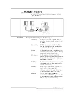
Page 27: ...ed from 25m to 10 000m facilitating remote or disaster tolerant sites Performance 100 Mbytes sec Fibre Channel 200 Mbytes sec bi directional offers increased bandwidth when distributing data across multiple SCSI devices Reliability Low error rates robust error recovery and flow control provide an enterprise with reliable data delivery Scalability Point to point links can be expanded to multi initi...

Page 28: ...edia can communicate with each other It attaches to either a Fibre Channel or SCSI host and transfers the command data and status information to SCSI or Fibre Channel targets The host passes packets to SCSI or Fibre Channel targets as if the FCR200 were just another device along the path The FCR200 provides connections for two SCSI buses and a Fibre Channel Arbitrated Loop or Switched Fabric It ta...

Page 29: ... as a SCSI initiator passing requests from hosts on the Fibre Channel network to target devices on the SCSI bus Each FCR200 SCSI bus uses a single SCSI ID The default ID is 7 and can be changed when configuring the FCR200 The Fibre Channel Side In a Fibre Channel loop the FCR200 is identified by a single Arbitrated Loop Physical Address AL_PA or a fabric assigned Source ID Once the address is acqu...

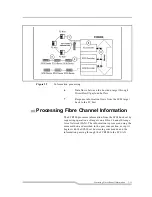
Page 30: ... Information The following describes how the router processes SCSI information Refer to Figure 2 7 on page 2 11 1 A FC host issues a command The FC host encapsulates the command in the FCP protocol and sends the packet to the FCR200 2 The FC port in the FCR200 receives the packet interprets the FC information and places the packet in buffer memory 3 The FCR200 s processor interprets the informatio...

Page 31: ...et back to the FC host Processing Fibre Channel Information The FCR200 processes information from the SCSI bus host by requesting operations of targets on a Fibre Channel Storage Area Network SAN The information is processed using the same method as described in the previous section except it begins with the SCSI host bus issuing commands and the information passing through the FCR200 to the FC SA...

Page 32: ...2 12 Description 62 9301 01 ...

Page 33: ...nding 3 3 Servicing 3 3 Warranty 3 3 German Statements 3 4 Sicherheitshinweise 3 4 Schutzerdung 3 4 Wartung Instandsetzung 3 4 Laser Safety 3 5 Certification and Classification Information 3 5 Product Information 3 7 Usage Restrictions 3 7 ...

Page 34: ...3 2 Safety 62 9301 01 ...

Page 35: ...hat the protection has been impaired disconnect the power cord until the ground has been restored Servicing Any servicing adjustment maintenance or repair must be performed only by authorized service trained personnel There are no operator serviceable parts in this product Warranty If you have any questions about the warranty of this product contact a sales representative WARNING A WARNING denotes...

Page 36: ...en Sie die Netzzufuehrung bis die Schutzerdung wieder einwandfrei ist Wartung Instandsetzung Jegliche Wartung Instandsetzung oder Einstellung muss durch einen qualifizierten authorisierten Fachmann durchgefuehrt werden Das Geraet enthaelt keinerlei zu wartende Teile fuer den Benutzer WARNUNG Eine WARNUNG bezieht sich auf eine Gefahr die zu Verletzung von Personen fuehren kann ACHTUNG Ein ACHTUNG b...

Page 37: ... J Outside the USA all GBICs are certified as Class 1 laser components that conform to the requirements contained in the International Electrotechnical Commission IEC standard 825 1994 and Amendment 1 1990 along with the CENELEC European Committee for Electrotechnical Standardization European Normalization standard EN 60825 1992 WARNUNG Das Netzteil ist bestimmt und zertifiziert fuer einen Netzspa...

Page 38: ...anstalt SP in Sweden The following shows the Class 1 information label specified in IEC 825 and CENELEC HD 482 51 This label is attached to this product The following information provides the typical operational parameters for the Optical Laser GBIC included with the FCR200 Parameter Shortwave Longwave Nomenclature 100 M5 SN I 100 SM LC L Spectral Centre Wavelength 770 850nm 1300nm Operating Range...

Page 39: ... in the wavelength of 780 or 1300 nanometers Usage Restrictions Failure to comply with these usage restrictions may result in incorrect operation of the system and points of access may emit laser radiation above the Class 1 limits established by the IEC and U S DHHS Nominal Bit Rate 1061 5 Mbaud 1062 5 Mbaud OFC none none Parameter Shortwave Longwave WARNING There are no user maintenance or servic...

Page 40: ...3 8 Safety 62 9301 01 ...

Page 41: ... 4 6 Slide Rail Mounting Optional 4 8 Interfaces and Connections 4 11 Fibre Channel Connection 4 12 SCSI Connection 4 15 Ethernet Connection 4 17 Serial Port Connection 4 18 Autobaud Feature 4 19 Connecting the Power Cord 4 20 Management Information Base MIB 4 21 MIB Fibre Channel Interface Information 4 21 MIB SCSI Interface Information 4 21 MIB Ethernet and Serial Interfaces Information 4 22 ...

Page 42: ...4 2 Installation 62 9301 01 ...

Page 43: ...clude the location of the unit the use of the unit and the type of devices to which the unit will be attached Location The FCR200 Router can be placed on a desktop or mounted in a standard 19 inch rack depending on the specific requirements of the installation The operating environment should meet the requirements found in Chapter 2 If you plan to use the router on a tabletop attach the stick on f...

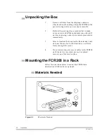
Page 44: ...n item is missing contact your sales representative immediately 3 Select a location that ensures the front intake vents and rear fan are clear of obstructions so air flows freely through the router 4 Do not connect any devices or cables to the FCR200 until the device is secured in a rack or placed securely on a flat level surface Mounting the FCR200 in a Rack Follow the directions below to mount t...

Page 45: ...4 5 1 FCR200 2 Left and right mounting rails optionl 3 Slide rails optional 4 Mounting screws 8 torx screws and 4 phillips screws and cage nuts 5 Left and right ears Required tools Phillips screwdriver Standard Torx screwdriver set ...

Page 46: ...re 4 2 Cage Nut Installation Ear Rail Mounting If you are mounting the FCR200 in the front of the rack with the connectors facing the back or in the back of the rack with the connectors facing the front attach the mounting ears using phillips screws as shown in Figure 4 3 on page 4 7 Note Place the FCR200 so the rear fan vent and the front intake vents remain clear of obstructions to ensure proper...

Page 47: ...ront of the rack with the connectors facing the front or in the back of the rack with the connectors facing the back attach the mounting ears as shown in Figure 4 4 Figure 4 4 Mounting at back of Rack 1 Attach each bracket to the mounting rail using two torx screw on each side Tighten the screws securely ...

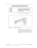
Page 48: ...ounting rails using two torx screws on each side Be sure to use only the top and bottom holes in each bracket The middle holes will be used to attach the front cover panel after the unit is installed Tighten the screws securely WARNING To reduce injury or equipment damage the mounting bracket must be level If the brackets are not level the FCR200 cannot be installed properly ...

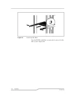
Page 49: ...gure 4 6 Attaching the Brackets Figure 4 7 Attaching Brackets 3 Attach the slide rails to the FCR200 using two torx screws on each side Slide the unit back into the rack and push in on the front tabs until the rails snap into place ...

Page 50: ...4 10 Installation 62 9301 01 Figure 4 8 Attaching Side Rails Once the FCR200 is installed you are ready to connect it to the other system components ...

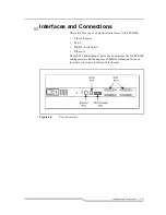
Page 51: ... types of physical interfaces to the FCR200 Fibre Channel SCSI RS 232 Serial port Ethernet The RS 232 and Ethernet ports are used primarily for FCR200 configuration and management MIB information for each interface is discussed later in this chapter Figure 4 9 Port Locations ...

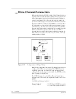
Page 52: ...or target device in a point to point fashion Arbitrated loops also allow for the use of Fibre Channel hubs to which the unit can be directly attached In Fibre Channel switched environments the switch is directly attached to the FCR200 Figure 4 10 Configuration with Tape library Both switches and hubs may allow for individual ports to be configured for different media types The FCR200 must be conne...

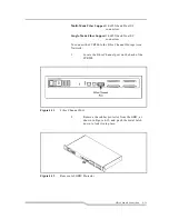
Page 53: ...ual SC connectors To connect the FCR200 to the Fibre Channel Storage Area Network 1 Locate the Fibre Channel port on the back of the FCR200 Figure 4 11 Fibre Channel Port 2 Remove the rubber protector from the GBIC as shown in Figure 4 12 and push the metal latch down to lock it into place Figure 4 12 Removal of GBIC Protector ...

Page 54: ...g the appropriate cabling The connectors on the FCR200 are keyed Be sure to insert the cable connectors in the proper orientation WARNING The FCR200 has been qualified with a specific set of GBICs Using a GBIC that has not been qualified may cause the FCR200 to operate improperly or to void approval and certifica tions ...

Page 55: ...e fault is cleared To connect the FCR200 to a SCSI bus 1 Power off your SCSI devices 2 Connect a SCSI cable to one of the SCSI connectors on the back of the router If necessary use a narrow to wide adapter 3 Connect the other end of the SCSI cable to the next SCSI device on the bus 4 If the FCR200 is at the end of the SCSI bus place the terminator provided with the router on the FCR200 s other SCS...

Page 56: ...nnection 5 Make sure that each bus is terminated correctly The device at each end of each bus must be terminated Figure 4 14 SCSI Terminator 6 Power on your SCSI devices 7 After all the SCSI devices have completed their individual POSTs power on the FCR200 ...

Page 57: ...guration is required to set the IP network address to allow for use of the configuration capabilities of this port Refer to Chapter 6 for details on setting the IP network address Ethernet capabilities include Telnet for configuration FTP and TFTP for firmware upgrades and SNMP for configuration and management Figure 4 15 FCR200 Ethernet Port Note The FCR200 contains a unique Ethernet MAC address ...

Page 58: ...update the program stored in the FCR200 s Flash memory A cable is provided with the unit to connect to a DB 9 serial connection Further information on the operations allowed via the RS 232 port is provided in Chapter 6 The RS 232 port operates with the following settings Baud Rate Autobaud 9600 19200 38400 57600 or 115200 Data Bits 8 Stop Bits 1 Parity None Flow Control None Figure 4 16 FCR200 Ser...

Page 59: ... detect the baud rate and configure the router The baud rate is then saved in the FCR200 s configuration and will be retained through future power cycles The baud rate in the terminal emulation program must be set at 9600 19200 38400 57600 or 115200 for the autobaud feature to recognize it The FCR200 will not function properly at any other baud rate Note Hitting the Enter key before the POST has c...

Page 60: ... use the FCR200 outside of the U S or Canada you must supply your own power cord To connect the power cord to the FCR200 1 Make sure the FCR200 s power is switched off See Figure 4 17 for the location of the power switch on the back of the router 2 Connect the female end of the power cord to the power connector on the back of the FCR200 3 Plug the male end of the power cord into the power source F...

Page 61: ...nel Interface Information Fibre Channel data reported includes frame and packet information upper layer protocol ULP type FCP or IP and other Fibre Channel specific information Draft MIBs for Fibre Channel N_Ports and F_Ports are in the public domain The ADIC private MIB includes Groups for Fibre Channel configuration Fibre Channel port physical table Fibre Channel port statistics SCSI to Fibre Ch...

Page 62: ...net interface is used for configuration and management so total traffic flow is relatively low The basic Ethernet configuration items are found in the Management Interfaces MI Table The serial port is provided for user configuration The serial port baud rate will be kept in the MI Table ...

Page 63: ...ibre Channel Configuration 5 4 Soft Addressing 5 4 Hard Addressing 5 4 General SCSI Configuration 5 5 Fibre Channel Host to SCSI Target Configuration 5 5 Address Mapping 5 5 Indexed Addressing 5 6 Auto Addressing 5 7 SCC Addressing 5 8 SCSI Host to Fibre Channel Target Configuration 5 8 ...

Page 64: ...5 2 Understanding the Configuration 62 9301 01 ...

Page 65: ...sts communicating with Fibre Channel targets Other functions and features can be configured as well and are discussed further in this chapter A typical configuration would have a Fibre Channel host connecting via an arbitrated loop to the FCR200 with SCSI target devices attached to the FCR200 This configuration using a tape library and drives is represented in Figure 5 1 The factory default config...

Page 66: ...orts up to 126 devices on an arbitrated loop Hard Addressing When acquiring a hard address the FCR200 attempts to acquire the AL_PA value that was specified by user configuration If the desired address is not available at loop initialization time the FCR200 comes up on the loop in non participating mode This allows the loop to continue to operate although the unit will not be accessible via the Fi...

Page 67: ...ates for the maximum values for transfer rates and data width on a SCSI bus If an attached device does not allow the full rates the unit will use the rates negotiated for that device Negotiation is on a device specific basis so the unit can support a mix of device types on the same bus Fibre Channel Host to SCSI Target Configuration This section describes the configuration of the FCR200 when actin...

Page 68: ...ulting to ID 7 All commands passed through to a SCSI bus originate from this SCSI ID As an example SCSI bus 0 corresponds to SCSI port 0 on the rear of the FCR200 SCSI bus 1 corresponds to SCSI port 1 Indexed Addressing Indexed Addressing allows for generic Fibre Channel host bus adapters to access SCSI devices attached to the FCR200 This is done by use of a table which is indexed by sequential FC...

Page 69: ... thereby changing the order of devices on a SCSI bus Auto Addressing The Auto Addressing option is similar to Indexed Addressing but with the distinction that the table used is created through SCSI device discovery upon power up or reset and not otherwise retained As the unit performs device discovery on a SCSI bus the Index table is filled with adjacent FCP LUNs referencing each subsequent SCSI d...

Page 70: ...routed to the appropriate SCSI BUS TARGET LUN and processed accordingly Further description of the FCR200 implementation of SCC addressing is in Appendix D SCSI Host to Fibre Channel Target Configuration This section describes the configuration of the FCR200 when acting as a target to a SCSI Initiator passing requests through to Fibre Channel targets SCSI to Fibre Channel mapping is implemented in...

Page 71: ...the SCSI configuration menu Target ID s enabled for the FCR200 must be unique on the SCSI bus with the exception that the initiator ID used on the FCR200 should also be used as a single target ID For example in SCSI to Fibre Channel mode one of the targets must have the same ID as the FCR200 0 4 1 0x10 0 0 4 2 0x17 0 0 4 3 0x18 0 Table 5 2 SCSI to Fibre Target Channel Address Mapping SCSI BUS TARG...

Page 72: ...5 10 Understanding the Configuration 62 9301 01 ...

Page 73: ... Fibre Channel Configuration 6 11 SCSI Configuration 6 12 Ethernet Configuration 6 13 Fibre Channel to SCSI Mapping Configuration 6 13 Changing the Fibre Channel to SCSI Mapping Mode 6 14 SCSI to Fibre Channel Mapping Configuration 6 15 Trace Settings Configuration 6 15 Save Configuration 6 15 Restore Last Saved Configuration 6 15 Reset Configuration to Factory Defaults 6 16 Display POST Status 6 ...

Page 74: ...n 62 9301 01 Configuring the FCR200 s Ethernet Port 6 20 SNMP Configuration 6 21 Toggle Trap 6 21 SNMP Configuration with Traps Enabled 6 22 GET and SET Community Names 6 22 IP Address for Traps 6 22 Trap Priority 6 22 ...

Page 75: ...NMP and telnet The FCR200 Configuration Program allows the user to control many configuration settings through the FCR200 serial interface Among these are Baud rate of the serial port Fibre Channel address SCSI initiator and target IDs Ethernet IP and MAC addresses Fibre Channel to SCSI mapping SCSI to Fibre Channel mapping Trace level settings Configuration settings may be changed and saved Note ...

Page 76: ...en power is applied to the router Fault This amber indicator lights up during POST then remains dark unless the FCR200 experiences a processor problem SCSI 1 This green indicator signifies SCSI 1 activity when lit SCSI 0 This green indicator signifies SCSI 0 activity when lit Fibre Channel This green indicator signifies Fibre Channel activity when lit Ethernet This green indicator signifies Ethern...

Page 77: ...the operating system or most applications there are cases where older applications can have expectations about what are valid SCSI ID s and not deal correctly with certain mappings In particular applications have been seen to have difficulties addressing target ID s greater than 15 e g 16 and up This problem can be resolved by configuring the FCR200 to use hard addressing and setting the AL_PA use...

Page 78: ...s which are not accessible via the serial interface SNMP support also includes Traps which are used to notify a SNMP management console of various conditions The objects defined in the ADIC private MIB are specific to the ADIC products For a copy of the ADIC private MIB contact a service representative Communicating with the FCR200 The FCR200 is designed to function directly out of the shipping co...

Page 79: ... program to use the appropriate COM port 4 Specify the following settings for the port Baud rate 9600 19200 38400 57600 or 115200 Data bits 8 Parity None Stop bits 1 Flow control None 5 Power on the FCR200 Table 6 1 Connection Properties Type Setting Baud rate 9600 19200 38400 57600 or 115200 a a For more information on the Autobaud feature refer to Chapter 4 Date bits 8 Parity None Stop bits 1 Fl...

Page 80: ...CI Protocol RAM 16Mb passed SCSI Script RAM I passed SCSI Script RAM II passed Initialize Ports Fibre channel port Single frame Sequence Loopback passed Fibre channel port Multiple frame Sequence Loopback passed Ethernet Port Loopback passed SCSI Port I Loopback passed SCSI Port II Loopback passed Self test completed successfully Select which mode to boot 1 Fibre Channel SCSI Router 2 Diagnostic M...

Page 81: ...arious operations to be performed on the FCR200 FCR200 Configuration Version X X XXXX 1 Perform Configuration 2 Display Status of Power on Self Test 3 Display Trace and Assertion History 4 Reboot 5 Download a New Revision of the Firmware Command ...

Page 82: ... Enter uppercase and lowercase characters interchangeably when selecting from menus Configuration Menu Version X X XXXX 1 Baud Rate Configuration 2 Fibre Channel Configuration 3 SCSI Configuration 4 Ethernet Configuration 5 Fibre Channel to SCSI Mapping Configuration 6 SCSI to Fibre Channel Mapping Configuration 7 Trace Settings Configuration A Save Configuration B Restore Configuration C Reset Co...

Page 83: ...dress method hard address value and WWN overrides When configuring the Fibre Channel AL_PA the FCR200 will present a list of loop addresses along with the corresponding AL_PA The user selects the loop address desired Baud Rate Configuration Menu Version X X XXXX 1 9600 2 19200 3 38400 4 57600 5 115200 X Return to previous menu Fibre Channel Configuration Menu Version X X XXXX Current Fibre Channel...

Page 84: ... modify the mapping table for that device SCSI Configuration Menu Version X X XXXX Bus 0 Current SCSI Configuration Initiator SCSI ID 7 Target SCSI ID s Reset SCSI Bus on Boot Yes 1 Change Initiator SCSI ID 2 Add Target SCSI ID 3 Remove Target SCSI ID 4 Toggle SCSI Reset Operation X Return to previous menu SCSI Configuration Menu Version X X XXXX Bus 1 Current SCSI Configuration Initiator SCSI ID ...

Page 85: ...nt Ethernet Configuration Ethernet Physical Address 30 30 45 30 30 32 IP Address 38 152 100 150 Subnet Mask 255 255 255 0 1 Change Ethernet Physical Address 2 Change IP Address 3 Change IP Subnet Mask 4 Change SNMP Settings 5 Change security Settings X Return to previous menu Fibre Channel to SCSI Configuration Menu Version X X XXXX Current Fibre Channel to SCSI Mapping Mode is Indexed 1 Display A...

Page 86: ...annel to SCSI mapping mode on the FCR200 The options are SCC addressing Indexed addressing and Auto addressing Auto addressing allows you to assign one of three mapping priorities LUN priority fills the table according to ascending LUN order Target ID priority Fills the table according to ascending SCSI Target ID SCSI device address ID order Bus Number priority Fills the table in ascending SCSI Bu...

Page 87: ...his should not be modified in normal operation as performance degradation may result Further information on using this interface can be later in this chapter Save Configuration This option saves the current configuration state in FLASH and updates the saved previous configuration state Restore Last Saved Configuration This option restores the most recent previously saved configuration This can be ...

Page 88: ...w Status of Power on Self Test Version X X XXXX Serial Port Loopback passed Monitor flash Check Sum passed Program store Main RAM passed Trace Buffer in Main RAM passed PCI Protocol RAM passed SCSI Script RAM I passed SCSI Script RAM II passed Fibre channel port Single frame Sequence Loopback passed Fibre channel port Multiple frame Sequence Loopback passed Ethernet Port Loopback passed SCSI Port ...

Page 89: ...rface can be located in the troubleshooting section of this manual Reboot The reboot function restarts the FCR200 This will cause selected configuration options to take effect This will result in all current operations being interrupted Do not reboot the unit during normal operation Trace Dump Menu Version X X XXXX 1 Display Trace for Current Boot Cycle 2 Display Trace for Previous Boot Cycle 3 Di...

Page 90: ... 1 Use the Transfer Send File option in the terminal emulator utility 2 Select the location of the firmware Use the Browse button if you need help finding it 3 Make sure you select XMODEM as the protocol 4 Press the Send button 5 The firmware will begin to download When the download is complete the system verifies that the firmware image was successfully written to the FLASH memory and then reboot...

Page 91: ... sure Y N y Please begin xmodem firmware transfer ___________ transmit Firmware image via XMODEM Performing Power on Self Test Self Test completed successfully Select which mode to boot 1 Fibre Channel SCSI Router 2 Diagnostic Monitor Seconds left 1 1 Verifying Firmware Checksum Updating Firmware Target Name ADIC Attaching Network interface lnPci0 Done Attaching Network Interface lo0 Done NFS Clie...

Page 92: ...elnet session is connected When logging in for a telnet session use root as the user name and password as the password Upgrading the FCR200 s firmware You can use FTP or TFTP to send a new firmware image to the FCR200 If you plan to use the Ethernet port you must first configure its address You can set the physical address IP address and IP subnet mask The physical address is assigned to an Ethern...

Page 93: ...le Trap SNMP Trap Enable allows Trap reporting to be turned on and off If SNMP Traps are disabled no Trap events are sent Press 3 to enable Trap events SMNP Configuration Menu Version X X XXXX Current SNMP Configuration Community Name for GET pub Community name for SET priv Traps are Disabled 1 Change Community Name for GET 2 Change Community Name for SET 3 Toggle Trap X Return to previous menu ...

Page 94: ...ypically this is the IP address of the machine using the Network Management Program and or a MIB browser Trap Priority The SNMP Trap Priority determines which traps will be sent to the specified Trap IP Address Events having a priority equal to or higher than the configured priority will be sent first SMNP Configuration Menu Version X X XXXX Current SNMP Configuration Community Name for GET pub Co...

Page 95: ... SCSI Bus Configuration 7 4 Verify Fibre Channel Connection 7 5 Verify SCSI Devices in NT 7 5 Verify Configuration 7 6 Verify Addressing 7 6 Verify Devices 7 6 Verify Host Configuration 7 6 Verify HBA Device Driver Information 7 6 RS 232 Port Problems 7 7 Contact Customer Support 7 7 ...

Page 96: ...7 2 Troubleshooting 62 9301 01 ...

Page 97: ...it or an internal problem with the unit The Fault indicator is lit when the FCR200 detects a fault condition Faults can occur as a result of Power On Self Test POST failure or operational failures It is normal for this indicator to flash on when the unit is powered up or reset If the fault indicator stays lit contact customer support The SCSI 1 indicator shows SCSI 1 activity when lit This should ...

Page 98: ...uration menu to view attached SCSI devices See Chapter 6 for more information Other conditions to look for include Termination Problems with termination can cause intermittent or hard failure A SCSI bus must be terminated on both ends and only both ends Termination issues when both narrow and wide devices are on the same bus are common Bus Type Single Ended devices cannot be mixed with Differentia...

Page 99: ...cted to a functional host disconnecting then reconnecting the Fibre Channel cable should cause momentary activity of this indicator as the link re initializes Also verify that the media type of the FCR200 and attached hub HBA or switch are of corresponding types When using optical media verify that the attached device is using non OFC type optical devices Verify SCSI Devices in NT If running FC to...

Page 100: ...re attempting to use to the native interface to verify that the devices are functional SCSI target devices can be connected to a host SCSI bus to verify they are functional Verify Host Configuration In some cases it may be that the host bus adapter or driver may not be working properly Check the configuration of these elements It may be useful to check the release notes for the driver provided to ...

Page 101: ...k the cabling or try a different host If a valid Ethernet IP address is configured RS 232 configuration settings can also be set via SNMP and telnet Contact Customer Support If you are unable to resolve your issue contact your service representative Customer support may ask that you provide trace data or other configuration information Trace data is obtained by setting the appropriate trace levels...

Page 102: ...7 8 Troubleshooting 62 9301 01 ...

Page 103: ...A Ethernet Assignments RJ 11 Serial and RJ 45 Ethernet Pin Assignments A 3 ...

Page 104: ...A 2 Ethernet Assignments 62 9301 01 ...

Page 105: ...gnments Figure A 1 RJ 11 Pin Assignment Pin Number Function Pin 1 No Connection Pin 2 Ground Pin 3 Transmit Data from FCR200 Pin 4 Receive Data to FCR200 Pin 5 RTS Ready to Send Pin 6 CTS Clear to Send Pin Number Function Pin 1 Transmit Out Pin 2 Transmit Out Pin 3 Receive In Pin 4 No Connection ...

Page 106: ...A 4 Ethernet Assignments 62 9301 01 Figure A 2 RJ 45 Pin Assignment Pin 5 No Connection Pin 6 Receive In Pin 7 No Connection Pin 8 No Connection Pin Number Function ...

Page 107: ...B Fibre Channel Interface and Commands Fibre Channel Interface and Commands B 3 Download Command B 3 Report LUNs Command B 5 PRLI Data B 6 ...

Page 108: ...B 2 Fibre Channel Interface and Commands 62 9301 01 ...

Page 109: ...date Firmware is successful when the FCP response returns 0x00 success When the download process is complete and the firmware image has been successfully written to FLASH the FCR200 will respond to the last transfer with 0x00 then re boot with the updated firmware If any errors occur the Controller will return an FCP_RSP response RC value other than 0x00 and the FCR200 will abort the update In thi...

Page 110: ...t data block is transferred mode 0x07 the FCR200 terminates data transfer and performs a CRC checksum on data received It is required that the FC initiator sends from the beginning of the firmware image to the end No out of sequence Write Buffers are allowed If the CRC test is successful the Controller will reboot The FCR200 will use the newly updated firmware If the CRC test fails the image trans...

Page 111: ...eive commands The format of the report LUNs command is as follows Table B 2 Report LUN Command Bits Bytes 7 6 5 4 3 2 1 0 0 Operation Code 0xA0 1 Reserved 2 Reserved 3 Reserved 4 Reserved 5 Reserved 6 9 MSB Allocation Length LSB 10 Reserved 11 Code Byte Table B 3 Report LUN Parameter List Bits Bytes 7 6 5 4 3 2 1 0 0 3 MSB LUN List Length LSB 4 Reserved 5 Reserved 6 Reserved 7 Reserved LUN List ...

Page 112: ... LUN Last LUN Table B 4 FCR200 PRLI Response Data PRLI Command Code 0x20 Page Length 0x10 Payload Length 0x10 Type Code 0x8 Type Code Extension 0x0 OPA 0x0 RPA 0x0 IPE 0x1 Response Code 0x1 Originator Process Associator 0x0 Responder Process Associator 0x0 Initiator Function 0x1 Target Function 0x1 Command Data Mixed Allowed 0x0 Data Response Mixed Allowed 0x0 Table B 3 Report LUN Parameter List B...

Page 113: ...Fibre Channel Interface and Commands B 7 Read XFER_RDY Disabled 0x1 Write XFER_RDY Disabled 0x0 Table B 4 FCR200 PRLI Response Data ...

Page 114: ...B 8 Fibre Channel Interface and Commands 62 9301 01 ...

Page 115: ...C SCSI Interface and Commands SCSI Interface and Commands C 3 SCSI Inquiry Data C 3 ...

Page 116: ...C 2 SCSI Interface and Commands 62 9301 01 ...

Page 117: ...ed to the FCR200 Table C 1 FCR200 Inquiry Data Peripheral Qualifier 0x00 Peripheral Device Type 0x0C Indicates Bridge Router function RMB 0x00 Device Type Qualifier 0x00 ISO Version 0x00 AENC 0x00 TrmIOP 0x00 Response Data Format 0x02 SCSI 2 Inquiry Data Format Additional Length 0x20 RelAdr 0x00 Wbus32 0x00 Wbus16 0x00 Sync 0x00 Linked 0x00 CmdQue 0x00 SftRe 0x00 Vendor ID CROSSRDS Product ID FCR2...

Page 118: ...d Commands 62 9301 01 The FCR200 will only reply to a SCSI Inquiry when using 8 byte LUN field of 0x00 s Once the FCR200 has been detected then the devices on the SCSI 2 can be detected using the SCC Logical unit addressing ...

Page 119: ...D Addressing Structures and Operation Addressing Structures and Operation D 3 SCC Addressing Option D 5 Indexed Addressing Option D 6 Auto Assigned Addressing Option D 7 ...

Page 120: ...D 2 Addressing Structures and Operation 62 9301 01 ...

Page 121: ...on the loop Device discovery is performed and an FCP target device list is built Each device is queried for FCP logical units The logical units are the actual devices that the operating system will address When an initiator addresses a logical unit the LUN field used is consistent in form with the SCC defined fields All current Fibre Channel host bus adapter drivers are consistent with these metho...

Page 122: ...52 63 0x74 84 0xA6 105 0xC9 1 0x02 22 0x31 43 0x53 64 0x75 85 0xA7 106 0xCA 2 0x04 23 0x32 44 0x54 65 0x76 86 0xA9 107 0xCB 3 0x08 24 0x33 45 0x55 66 0x79 87 0xAA 108 0xCC 4 0x0F 25 0x34 46 0x56 67 0x7A 88 0xAB 109 0xCD 5 0x10 26 0x35 47 0x59 68 0x7C 89 0xAC 110 0xCE 6 0x17 27 0x36 48 0x5A 69 0x80 90 0xAD 111 0xD1 7 0x18 28 0x39 49 0x5C 70 0x81 91 0xAE 112 0xD2 8 0x1B 29 0x3A 50 0x63 71 0x82 92 0x...

Page 123: ...s a controller device The host will then know on this basis that subsequent commands to attached devices will use the Logical Unit Addressing method The host can perform discovery by either walking through the BUS TARGET LUN values as would a standard SCSI driver or by issuing a REPORT LUNS command Appendix B This command is sent to the controller using the Peripheral Device Addressing Method and ...

Page 124: ...imes the number of targets per bus less one initiator ID per bus times the number of LUNs per target The index table can be manually edited Configuration tools allow for the table to be filled in order of increasing bus target or LUN as may be desired for the specific requirements needed A method is also provided to perform device discovery and fill the table in the order that devices are discover...

Page 125: ...lating FCP LUN values is filled with adjacent FCP LUNs referencing each subsequent SCSI device The host system will then detect every attached device without voids allowing full device discovery to the host This allows easy configuration in environments where device ordering is not important and hot plugging of SCSI devices will not occur Tape libraries are excellent candidates for using Auto Assi...

Page 126: ...D 8 Addressing Structures and Operation 62 9301 01 ...

Page 127: ...E Reference Standards Standards E 3 ...

Page 128: ...E 2 Reference Standards 62 9301 01 ...

Page 129: ...rect Attach FC PLDA Fibre Channel Arbitrated Loop FC AL ANSI X3T11 Project 960D Rev 4 54 Contact Globe Engineering 1 800 854 7179 GigaBaud Link Module GLM Family Fibre Channel System Initiative FCSI 301 Revision 1 0 Common FC PH Feature Sets Profiles Fibre Channel Systems Initiative FCSI 101 Rev 3 1 SCSI Profile Fibre Channel System Initiative FCSI 201 Rev 2 2 FCSI IP Profile Fibre Channel System ...

Page 130: ...E 4 Reference Standards 62 9301 01 ...

Page 131: ...d Mapping A menu item The auto addressing option creates a mapping table using devices discovered upon powering up or resetting the FCR200 that is not otherwise retained by the FCR200 B Baud The unit of signaling speed expressed as the maximum number of times per second the signal can change the state of the transmission line or other medium units of baud are sec 1 Note With Fibre Channel scheme a...

Page 132: ... on or comes on the FCR200 has a problem with one of its components During normal operation this LED should be off When the FCR200 is offline this LED blinks FC See Fibre Channel FC FC AL See Fibre Channel Arbitrated Loop FC AL on page gl 3 FC Adapter A printed circuit assembly that translates data between the FC host processor s internal bus and the FC link FC Device A device that uses Fibre Chan...

Page 133: ...Mounts on a FC adapter card and connects the FCR200 to a FC host Also referred to as a Physical Link Module PLM H Hardware Path See FC SCSI Hardware Path ID on page gl 2 Host Bus Adapter See FC Adapter on page gl 2 Indexed Addressing A menu name It allows for generic Fibre Channel host bus adapters to access SCSI devices attached to the FCR200 using a table which is indexed by sequential LUN value...

Page 134: ...a 64 bit value the factory assigns to the FCR200 O Offline Taking the FCR200 offline indicates that all SCSI and FC adapters in the FCR200 are offline Taking a SCSI adapter offline means ending inputs outputs and suspending all transactions going from the FCR200 to the specified SCSI devices The SCSI adapter is no longer active or available for access Taking a FC adapter offline means ending input...

Page 135: ... itself Each device has its own unique SCSI address The SCSI address of a device dictates the device s priority when arbitrating for the SCSI bus SCSI address 7 has the highest priority The next highest priority address is 6 followed by 5 4 3 2 1 0 15 14 13 12 11 10 9 8 with 8 being the lowest priority address The fast wide SCSI adapter is factory set to address 7 A narrow SCSI adapter supports up...

Page 136: ...ination at both ends of the bus One end of the SCSI bus is terminated by the SCSI adapter s internal termination The other end should have a terminator placed on the 68 pin high density SCSI connector on the last SCSI peripheral If this device is not terminated data errors may occur Topology The physical or logical layout of nodes on a network FC topologies include point to point FC AL and Fabric ...

Page 137: ...6 11 Fibre Channel to SCSI 6 13 Restore Last Save Configuration 6 15 Restore to factory 6 16 Save Configuration 6 15 SCSI 6 12 SCSI to Fibre Channel 6 15 Trace Setting 6 15 Configuration Features 2 4 Configuring SNMP 6 21 Get and Set Community Names 6 22 Toggle Trap 6 21 Trap IP Address 6 22 Trap Priority 6 22 Configuring the FCR200 6 3 Customer Support 7 7 D Desktop Mounting 4 3 Device Addressing...

Page 138: ...Features 2 4 Management Information Base MIB 4 21 Ethernet Information 4 22 Fibre Channel Information 4 21 SCSI Interface Information 4 21 Serial Interface 4 22 Mapping Devices 2 10 Multiple Initiators 2 7 N Non Operating Environment 2 5 O Operating Environment 2 5 Operation 2 8 D 3 SCSI and Fibre Channel 2 9 Fibre Channel Side 2 9 Mapping Devices 2 10 SCSI Side 2 9 Operator Indicators 6 4 Organiz...

Page 139: ...oggle Trap 6 21 Trace and Assertion History 6 17 Trace Setting 6 15 Trap IP Address 6 22 Trap Priority 6 22 Troubleshooting 7 3 Basic Verification 7 4 RS 232 Port Problems 7 7 Verify Addressing 7 6 Verify Configuration 7 6 Verify Device 7 6 Verify Fibre Channel Connection 7 5 Verify HBA Device Driver Info 7 6 Verify Host Configuration 7 6 Verify SCSI Bus Configuration 7 4 Verify SCSI Device in NT ...

Page 140: ...in 4 Index 62 9301 01 ...

Reviews: