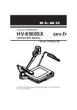
OPERATING AND USER MANUAL Q-12 CoaXPress series
________________________________________________________________________________________________________________
_________________________________________________________________________________________
Adimec
18
6 FUNCTIONAL DESCRIPTION
This chapter contains a functional description of the Q-12A180 camera. It briefly describes the main functions
and features of the camera using a simplified block diagram. More in-depth explanations on these functions as
well as descriptions on how to control them can be found in the next chapters of this manual.
6.1 Block diagram
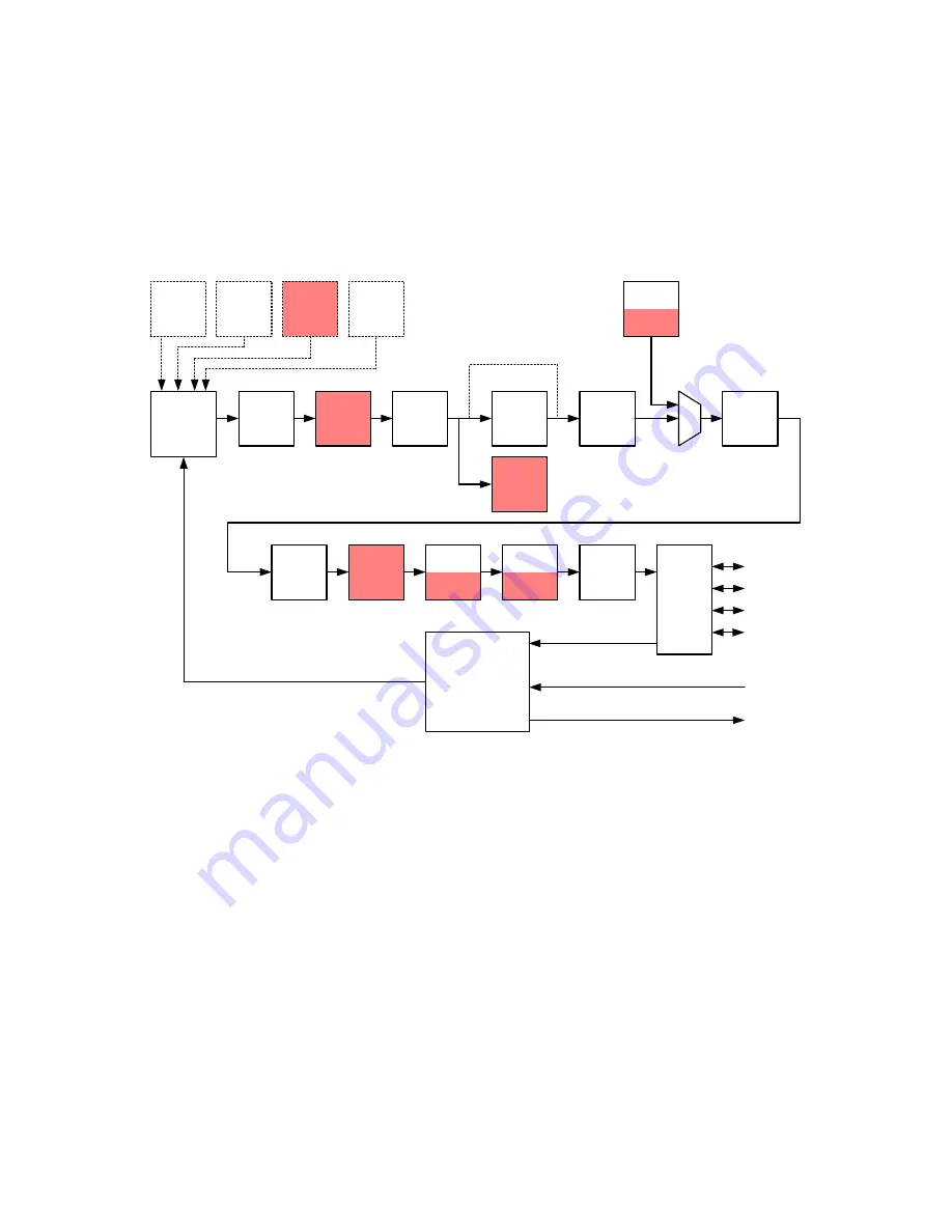
The diagram below shows the main functional blocks of the Q-12A180 camera.
Image
Sensor
BLC
1
Col.
FPNC
Test
Pat.
I/O Trigger-IN
I/O Stobe-OUT
LUT
CXP
IF
CXP(0)
CXP(1)
CXP(2)
CXP(3)
Device trigger
Hor.
Mirror
Insert
Crossh
Hor.
Crop
Trigger &
Sensor
control
White
Bal.
DPC
mono
Gain &
Offset
LF FFC
Proc
LF FFC
Meas
Band
Vert.
Crop
Vert.
Mirror
Binning
2
3
4
6
7
8
9
10
11
12
7
2
13
3
14
15
16
17
HDR
5
Figure 6-1: Block diagram of the camera. The dashed blocks are sensor functions. The solid blocks are camera
functions. The functionality in the red blocks is only available in Issue 2 cameras.
1. An AMS CMV12000 sensor is used in this camera.
2. The output image can be mirrored horizontally and vertically.
3. A Region of Interest (ROI) can be defined by using the vertical and horizontal crop functionality. The
camera will only output video information from a programmable rectangular sub frame. This reduces the
amount of data and can increase the frame rate.
Issue 2 only – The increment in width has been reduced from 32 to 16. The increment in OffsetX has
been reduced from 16 to 8. This adjustment allows to enable the black clamp and at the same time
leave them outside the output image with the largest resolution possible.
4. Issue 2 only - The Band function generates a rectangular image from a set of configurable bands.
5. HDR - High Dynamic Range - With this function an optical high dynamic range can be realized by using
the multi slope feature of the sensor.
6. BLC - Black Level Clamp - The Black Level Clamp function clamps the black level per line using the dark
reference columns if this function is enabled.


