OPERATING AND USER MANUAL OPAL-FAMILY
39
IMAGE CAPTURING AND VIDEO OUTPUT
Image Aquisition in normal control mode
7.6
In normal control mode camera timing is controlled by means of an external signal. The parameters
for integration time and frame period can still be set and read-out but have no meaning. Refer to
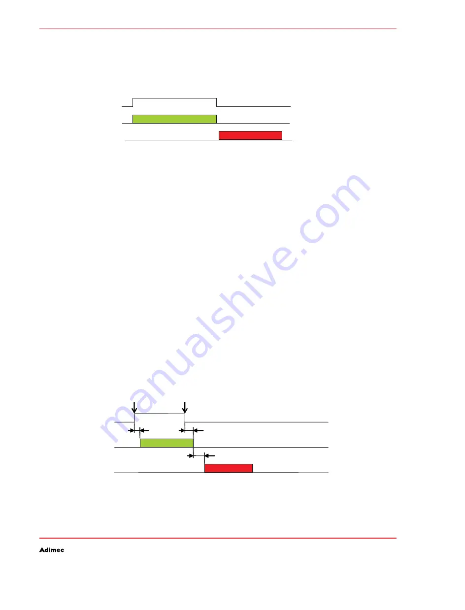
figure 7.4 for a simplified basic timing diagram.
Simplified example normal control mode
Figure 7.4:
The image integration starts at a rising edge of the trigger signal. Image integration stops at the falling
edge. Image read-out starts at the falling edge of the same trigger control signal.
Controlling the camera timing by means of (an) external signal(s) is possible by means of several
(combinations of) signals. The selection and behavior of the control signals are explained in detail in
par. 7.10 and 7.11. To simplify explanations in this chapter we will assume that image integration and
image read-out are controlled by only one external signal, i.e. the Camera Control signal #1 in the
Camera Link interface, referred to as CC1.
The rising edge of CC1 is interpreted as a “start integrating” request; the falling edge is interpreted as
both a “stop integrating” and a “start sending image data” request.
Taking into account the remarks and descriptions as mentioned in par 7.1, one can conclude the
following restrictions on the trigger signal:
The time between two falling edges of the read-out trigger signal must be equal or longer than the
•
minimum frame period valid for the image format programmed.
If a falling edge is detected too early, i.e. before the image is completely read out, then this event
is ignored.
To make use of the maximum speed possibilities of the camera it is generally necessary to
•
generate a rising edge of the trigger signal before the previous image is completely read out.
If the integration time needs to be varied while grabbing images continuously, make sure that the
control signal edge corresponding with start-of-integration is varied. In standard settings this is the
rising edge of the control signal. The falling edges of this signal must remain at constant time-
distances in order to prevent a too early “start sending image data” request. For timing details see
figure 7.5. See table 7.2 & 7.3 for the values of all timing parameters.
Timing details normal control mode.
Figure 7.5:
Integration image
Image read-out
CCD Operation
Camera Output
Control Signal
Exposure
control
Sensor
integration
Image
output
td_it_bgn
td_it_end
integrating
td_output
Output image
Exposure
Start event
Exposure
End event
exposure
Summary of Contents for Camera Link OPAL Series
Page 1: ...Operating and user manual OPAL FAMILY CAMERA LINK MODELS ...
Page 2: ...OPERATING AND USER MANUAL OPAL FAMILY 2 ...
Page 9: ...OPERATING AND USER MANUAL OPAL FAMILY 9 ...
Page 10: ...OPERATING AND USER MANUAL OPAL FAMILY 10 ...
Page 14: ...OPERATING AND USER MANUAL OPAL FAMILY 14 SAFETY INFORMATION ...
Page 22: ...OPERATING AND USER MANUAL OPAL FAMILY 22 ...
Page 30: ...OPERATING AND USER MANUAL OPAL FAMILY 30 ...
Page 34: ...OPERATING AND USER MANUAL OPAL FAMILY 34 ...
Page 86: ...OPERATING AND USER MANUAL OPAL FAMILY 86 REVISION HISTORY ...


