OPERATING AND USER MANUAL QUARTZ series CXP
15
Functional description
4.
This chapter contains a functional description of the Quartz cameras. It briefly describes the main
functions and features of the camera using a simplified block diagram.
More in-depth explanations on these functions as well as descriptions on how to control them are in
the next chapters of this manual.
Block diagram
4.1
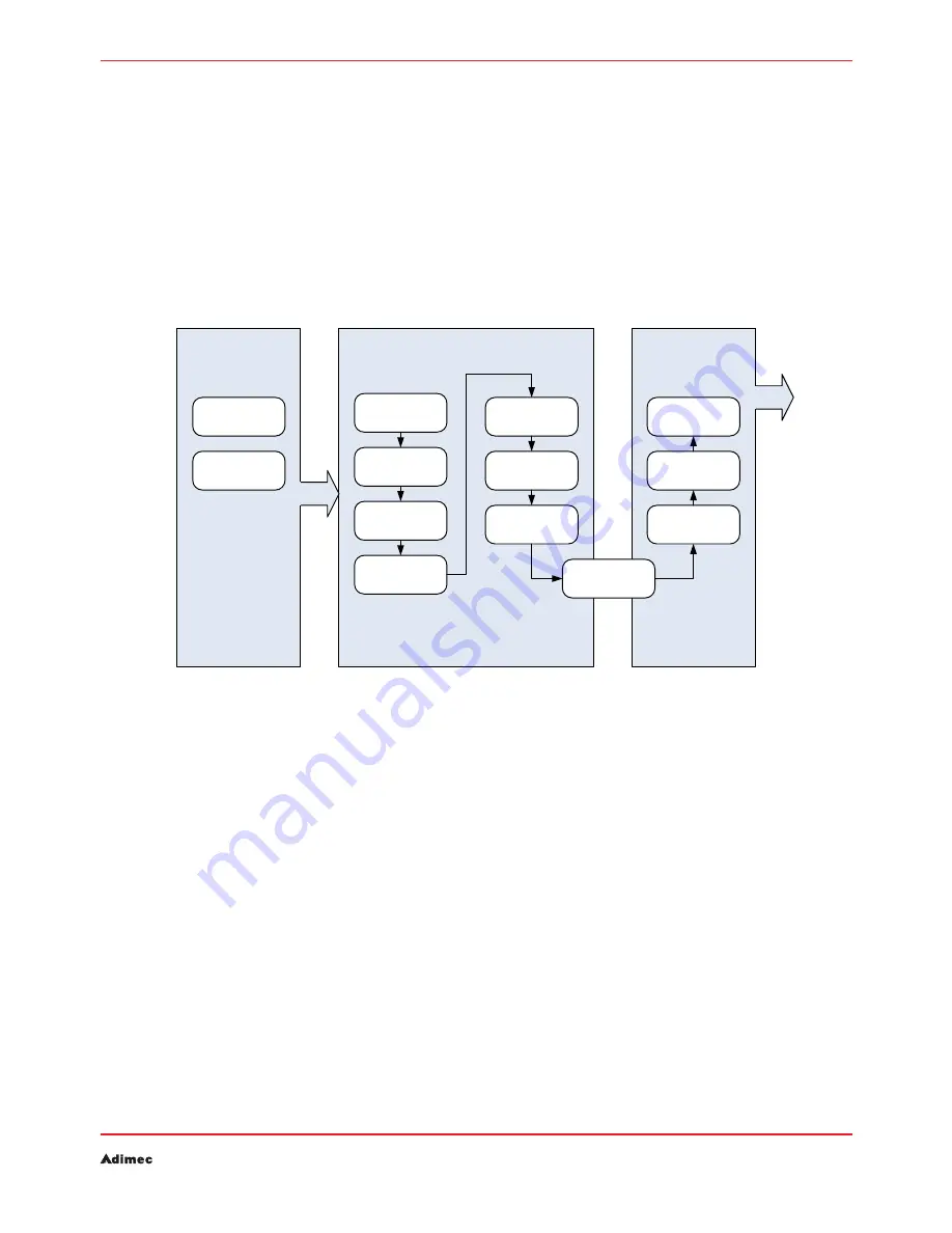
The diagram below shows the main functional blocks of the Quartz cameras.
Block diagram of the camera
Figure 4.1:
The CMOS image sensor is equipped with one analog to digital converter per column.
A Region Of Interest (ROI block) is available. The camera will only output video information from a
programmable rectangular sub frame. This reduces the amount of data and can increase the frame
rate.
The defect pixel correction function can be enabled and disabled on demand. Also, defect pixels can
be added to the list or removed by the user.
For functional testing of the camera and frame grabber chain, a test pattern generator is available. The
test pattern generator can be enabled and disabled on demand.
Flat field correction allows for correction of fixed pattern noise as well as shading. A full calibration
can be done in the field.
Digital Gain is applied within the basic processing block. An output look-up table is available; this
table allows real-time conversion of the video levels from the processing chain according to a user
programmable curve (e.g. Gamma-function).
Image Capture
Modes
ROI
Defect pixel
Correction
Test pattern
Flat field
Correction
Basic
Processing
Frame
Averaging
Binning
Image flip
Frame
Buffering
CoaXPress
Interface
Format
conversion
Image tagging
Image Capture
Image Processing
Image Output


