18
Adirondack Spas
®
OWNER'S MANUAL
inSTAllATion inSTrucTionS:
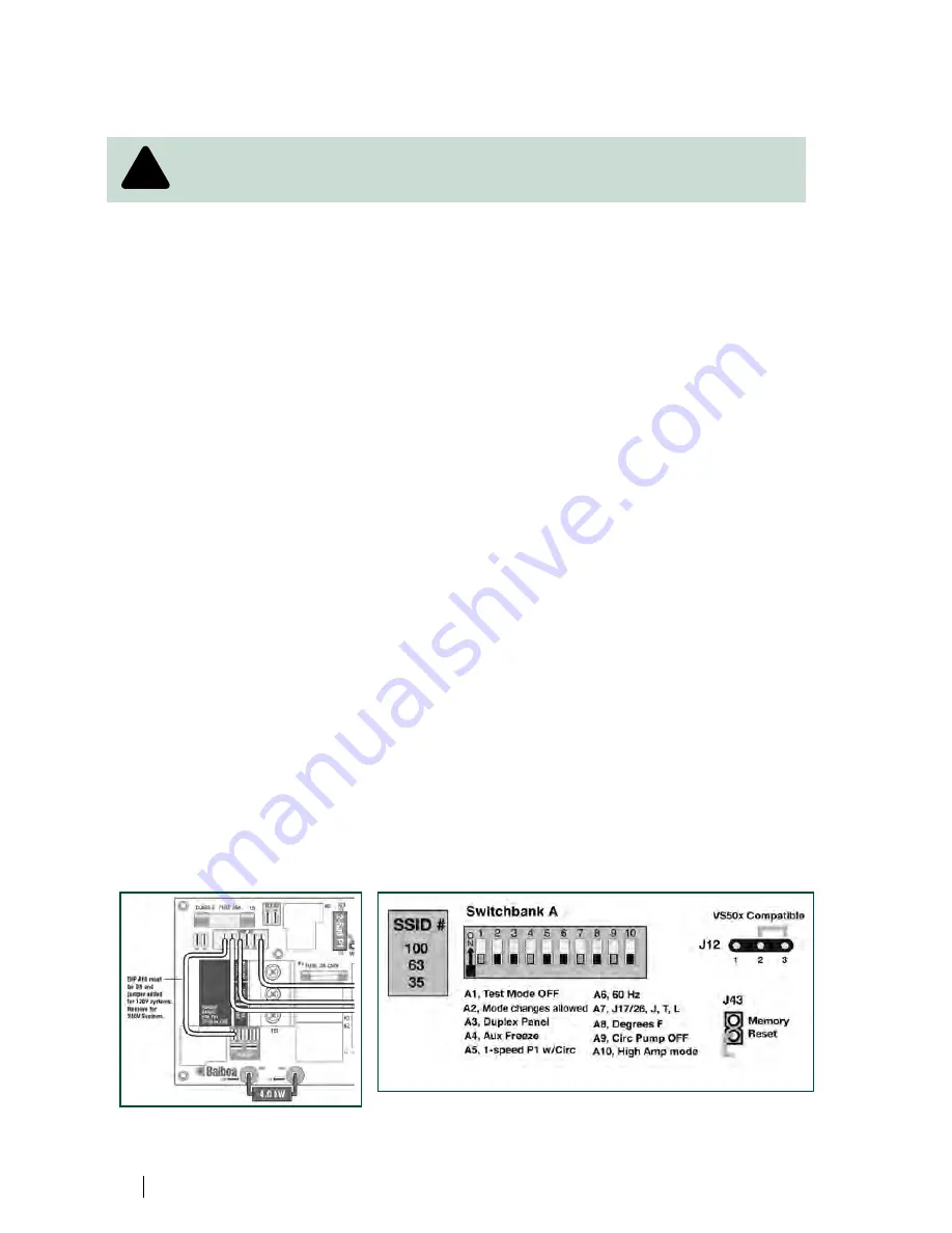
The following instructions are for the conversion of the Adirondack Spas® 110V/220V control
pack from a 220 Volt application to a 110 Volt application .
Due to the risk of equipment damage or fire, use only approved pressure-type wire
splicing lugs or connectors suitable for the size and type of wiring used .
Before servicing the spa, make sure all power to the spa is disconnected . Follow these instructions
for a successful electrical installation .
1 . Unscrew the screws on the front access panel .
2. Carefully pull access panel toward you (away from spa) and pull upward. Set access
panel aside .
3 . Locate the spa power pack . Loosen the screws on the front of the control box . Remove the
control box cover and the terminal block will be exposed .
4 . Route the GFCI power cord through the vent hole in the base of the equipment
compartment and out from under the corner of the spa .
Note: 110 Volt installations require a 60Hz, single phase, two-wire electrical service plus
ground (Line 1, Neutral and Ground) and must be connected using a minimum supply
conductor ampacity of 20 Amps and a minimum GFCI circuit breaker size of 20 Amps .
5 . Input the GFCI power cord to the terminal block inside the spa pack .
6 . Connect the 8 AWG WHITE wire, from the power cord, to the WHITE "NEU" terminal
on TB1 .
7 . Connect the 8 AWG BLACK wire, from the power cord, to the BLACK "HOT" terminal on
TB1 .
8 . Connect the 8 AWG GREEN wire, from the power cord, to the GREEN "GROUND"
location on the "BONDING LUGS" terminal .
9. Connect jumper wire (jumper wire taped to the back of the spa pack) to J11 and J32.
10 . Move dip switch #10 to the ON position .
11 . Replace the control box cover and securely tighten the fastening screws . Close and secure the
equipment compartment panel .
note:
Please review the back of the spa power pack cover, in the equipment bay, for a complete
spa wiring diagram .
!
!


