NEO FIRE – Technical Manual
63
17.4
Gas/air adjustments
All the boilers are tested in our factory and every one is supplied with a table indicating the combustion
figures. Both the start-up and the maintenance must be carried out by authorized technical staff.
First of all verify: electric supply, if the gas connection is air vented, type of gas and pressure, if the heating
demand is at the maximum value, correct draught of the chimney, if the hydraulic installation is vented, if the
pump is correctly working...
The process would be as follows:
First adjust the combustion at the minimum power (to avoid lockout).
Adjust combustion at the maximum power.
Adjust combustion at the minimum power.
Repeat the previous steps at the minimum and maximum power.
Once adjusted, check the combustion at the intermediate stages between the minimum and the maximum
power.
Any change in the gas shut-off valve produces a change in the combustion, both at the maximum and at the
minimum power. Check them alternatively until you reach the required combustion figures.
Check combustion in the main burner:
Ionization current (> 5 m microamperes): connect in series the meter to the ionization electrode and to its
electric connection.
Pressure: gas (Pg), combustion chamber (Pf), air-gas mix (Pa) (similar to the values indicated in the combustion
document issued in our factory).
Gas flow.
Combustion parameters: CO
2
, O
2
, CO, flues temperature, air temperature, efficiency, water temperatures.
Remember that these changes must be made by specialized technicians.
17.4.1
Combustion adjustment
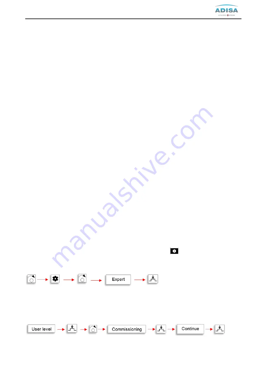
To adjust the power of the boiler to maximum and minimum and check the CO2 values, the controller stop
function must be activated. For this, proceed as follows:
On the navigation bar, turn the control knob until “Service/setting pages”
is preselected. Press the control
knob to enter to the page. In the work area, turn the control knob until operation object “Expert” is
preselected. Press the control knob and the login dialog box opens.
The user level setting is preselected. The Press the control knob. The user level is selected and is displayed
inverted. Turn the control knob to select “Commissining”. Press control knob to confirm selection. Message of
successful login opens and “Continue” is preselected. Press the control knob to confirm.
Summary of Contents for NEO FIRE 120
Page 1: ...TECHNICAL MANUAL OF INSTALLATION USE AND MAINTENANCE 07 2020 ...
Page 7: ...NEO FIRE Technical Manual 7 NEO FIRE 360 900 ...
Page 9: ...NEO FIRE Technical Manual 9 NEO FIRE 80 NEO FIRE 120 160 ...
Page 10: ...NEO FIRE Technical Manual 10 NEO FIRE 200 280 NEO FIRE 360 720 ...
Page 34: ...NEO FIRE Technical Manual 34 11 1 Electric drawing NEO FIRE 80 720 ...
Page 35: ...NEO FIRE Technical Manual 35 11 2 Electric drawing NEO FIRE 810 900 ...
Page 37: ...NEO FIRE Technical Manual 37 Electric drawing 1 Boiler with 3 heating circuits ...
Page 41: ...NEO FIRE Technical Manual 41 System drawing 1 Boiler and Domestic Hot Water DHWS ...
Page 58: ...NEO FIRE Technical Manual 58 System drawing D H W and heating circuit 11 11 ...
Page 59: ...NEO FIRE Technical Manual 59 System drawing of an old installation heating circuit 11 ...
Page 70: ...NEO FIRE Technical Manual 70 18 4 Position of probes and sensors ...


