background image

User Manual MIC 980


Issue 21.01.2019_01 


35 

16 

Technical data 

See data sheet  


17 

List of figures 


Figure 1: MIC 980 ...................................................................................................................................... 6


Figure 2: Key pad ..................................................................................................................................... 9


Figure 3: Numerical pad Eingabe ......................................................................................................... 10


Figure 4: Startpage (Standby) ............................................................................................................... 11


Figure 5: Menu ........................................................................................................................................ 12


Figure 6: Choice of programmes .......................................................................................................... 13


Figure 7: Favorites Readinessmode ..................................................................................................... 13


Figure 8: Alarm ....................................................................................................................................... 30


Figure 9: Information page .................................................................................................................... 30


Figure 10: Set date/time ......................................................................................................................... 31


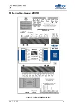
Figure 11: Connection diagram MIC 980 .............................................................................................. 34


Summary of Contents for MIC 900

Page 1: ...User Manual MIC 980 Stikkenoven V80 01 Stand 21 01 2019_01 ...

Page 2: ...Menu page 12 4 Programming mode 13 4 1 Program overview favourites 13 4 1 1 Compiling a list of favourites 14 4 2 Editing program steps 14 4 2 1 Program name 15 4 2 2 Select program image 15 4 2 3 Program steps 16 4 2 4 Nominal step values 16 4 2 5 Copying deleting and adding programs steps 17 4 3 Setting up a program with VisuNet 18 4 3 1 Enabling VisuNet 18 4 3 2 Editing programs with VisuNet 18...

Page 3: ...pened 29 10 Alarm signal 29 11 Information page 30 12 Profiles 31 12 1 Date and time 31 12 2 Enabling and disabling a signal 32 13 Power failure 33 14 List of errors possible problems 33 15 Connection diagram MIC 980 34 16 Technical data 35 17 List of figures 35 18 Index 36 19 Safety instructions 37 ...

Page 4: ...ollowing symbols are used in this user manual to emphasize important information Symbol Description This is a Please note or a tip Be aware This symbol points out potential problems and what to do to avoid them Shows a sequence of actions that should be executed one after the other ...

Page 5: ...nd below 1 2 1 Standby mode also see item 1 7 1 The controller is idling There is no temperature control and all outputs of the controller relays analogue outputs are inactive Hint Changes to the configuration settings and to some of the service and profile settings are only possible when the controller is in standby mode Certain aggregates can be switched on manually for a more detailed descripti...

Page 6: ...ting panel Be aware Please do not operate the touch screen with sharp implements i e pointed fingernails pens pencils screwdrivers etc Only use blunt soft implements i e fingers rubber pens The controller is sub divided into an input display panel and a control button panel 1 3 1 Input and display touch panel The upper half is a 7 touch display Here you can change the different settings and inform...

Page 7: ...ck to standby by pressing the Start page button on any page you may be on Air circulation Air circulation distributes warm air evenly throughout the oven so that the heat can reach the bakeware everywhere in the oven Press the button switch into a different level The current level is shown 0 air circulation is inactive I to III display shows the current level Symbol The air circulation motor is on...

Page 8: ...nt mode of the controller e g System not in operation readiness mode Night time pre heating If a running program was interrupted or terminated the operating mode display will be red and will be flashing 1 5 2 Display System status messages If the system status changes a message is shown A system status message and the current operating mode will be shown alternately 1 5 3 Display Remaining runtime...

Page 9: ...on screen key pad Figure 2 Key pad Insert replace mode Deleting individual symbols Deleting an entire text passage Capital Lower case letters Numbers and special symbols Confirm entry Leaving the operation without changing the original settings More special symbols ...

Page 10: ...ock All display functions are blocked when you press the Enter button during 3 sec On the lower margin of the display appears Lock To deactivate the look press the Enter button for 5 sec Please note The program processing is independent of screen lock If the screen lock is activated in operating mode the program will continue The activated screen lock has no influence on the communication with Vis...

Page 11: ...splay Logo Temperature values 1 Currently measured temperature 2 Nominal temperature for pre heating or readiness mode respectively Day and time for night time preheating Buttons for pre selecting and starting night time pre heating see item 5 Shortcuts and standby mode 1 Pre selecting the air circulation level for pre heating and readiness mode Air circulation remains switched off 2 Steam flap It...

Page 12: ...ervice Settings for the maintenance personnel on site Initial start up maintenance work etc The settings are protected by a password and can only be set up by a service technician Profiles Settings for the operator end user These settings are not password protected Programs Opens the program selection page item 4 Information Display of the information about the controller version and settings Star...

Page 13: ...ght Program set up change can start programming mode 4 1 Program overview favourites On the left hand side all programs are shown on a list On the left side the so called favourites are shown Favourites Programs that are started most frequently In readiness mode the favourites are offered first for a program start Function of the buttons Back to the start page standby Skipping backwards in the pro...

Page 14: ...k line in the favourites list you have to overwrite a program with an empty program without program name 4 2 Editing program steps Start on the Program selection display and highlight the program you want to edit by pressing on it Now press the Program button on the task bar Alternatively press the Edit button in the task bar In the next window press also the Edit button Date display Program line ...

Page 15: ...m 4 1 2 Skip back to the previous step 3 Skip forward to the next step 4 Menu page item 3 5 Return to the start page depends on the operating status of the controller 4 2 1 Program name Click on the box with the program name The on screen keypad will appear Enter name and confirm with Enter see item 1 6 4 2 2 Select program image By touching the Picture box separate images will appear Please selec...

Page 16: ... Standard name Entry range description Chamber Entry range 0 to 400 C Nominal value for temperature control If the measured temperature value is lower than the entered nominal value the heating will be switched on Baking time Entry range up to 99 59 hours minutes Step duration Nominal step time Steam time interval Entry range up to 999 seconds Time interval for feeding steam into the oven via the ...

Page 17: ...d levels of the air circulation motors 0 off 1 level 1 2 level 2 4 2 5 Copying deleting and adding programs steps Click on Prg box and select the action you want in this case copying Change to the Program selection display Press the Edit box on the task bar A selection window will open Press Copy 1 Settings Code 1004 parameter 1 for the extractor exhaust fan ...

Page 18: ...or aditec 4 3 2 Editing programs with VisuNet For how to edit programs with VisuNet please see the user manual VisuNet Base Comfort Premium Chapter 5 Entering changing copying and starting programs Be aware A program is automatically copied when you press Enter The program that originally occupied that position is overwritten Step number box Double click the Step number box and a menu window will ...

Page 19: ...de Day and time for night time pre heating Buttons 1 to 7 pre select day Button 8 starts pre heating mode If necessary the time of day and days of the week can be adjusted Waiting mode for pre heating active Controller is in waiting mode When the pre set time has arrived pre heating mode will automatically be started see item 6 Shortcut buttons Waiting mode 1 Pre select the air circulation level f...

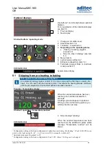
Page 20: ...ting Display for the pre heating time interval that has elapsed since pre heating was started Display for when the pre programmed nominal temperature has been reached When the temperature has been reached the horn will be switched on for 5 seconds2 Shortcut buttons Heating mode 1 Changing air circulation level 2 Steam flap item 1 4 3 Turntable is switched on 4 Starting readiness mode see item 7 5 ...

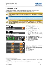
Page 21: ...tart program 1 Direct program number entry see item 1 7 2 Selecting a program from the list Step line Selecting a start program step2 3 Direct step number entry see item 1 7 Selecting a step from the list only valid steps are shown on the list see item 4 2 3 Temperature value 1 Currently measured temperature 2 Nominal temperature for the control process can be changed 3 Symbol when burner is activ...

Page 22: ...8 When you switch on the light manually M it will stay on until it is manually switched off 2 Configuration setting in the basic configuration Code 5052 Alarm 1 Setting can be changed 3 Nominal values can be changed in programming mode or in operating mode transient nominal value change Shortcut buttons readiness mode 1 Change air circulation level 2 Steam flap item 1 4 3 Turntable is switched on ...

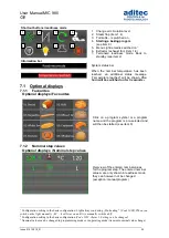
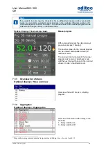
Page 23: ... the step is always pre set as process 2 Baking The nominal values for the manual program can be entered and adjusted directly in readiness mode The entered nominal values of the manual program only remain in readiness mode until the next manual change to the nominal values is made in readiness mode 7 1 3 Overview list of steps Optional displays Step overview Overview of all valid1 steps in a baki...

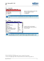
Page 24: ... list2 7 1 6 Notes Optional Displays Step overview Program notes for each program you cannot set up a list of notes for a manual program Hint A so called entry can be made for each program e g the recipe for a product For a detailed description see service manual Service settings Optional displays Notes 1 Overview of the status of the digital inputs which are connected to the controller 2 Overview...

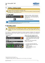
Page 25: ...ogram can be started Only administrators with the user right Program start can start a program The controller is in operating mode A program is currently in operation All aspects of the program are being controlled All the control outputs are actuated according to the programming configuration nominal step values Program line Display of the current program number name and program program symbol 1 ...

Page 26: ... the first step is usually Pre heat The Pre heat step has no baking time This means the heating process continues until the pre programmed nominal temperature has been reached Program Temperature display When the nominal temperature has been reached a horn will be activated for 5 seconds3 A baking symbol will appear in position 4 When you click on the baking symbol you will skip into the next step...

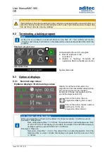
Page 27: ...ays 8 3 1 Nominal step values Optional displays Nominal step values Display for all the nominal values in a program and their associated actual values All nominal values can be changed transiently Change only applies until the end of the step see item 8 5 Click on the button the pre programmed baking time is reset Click on the button Steam nozzle is switched on for the pre programmed time interval...

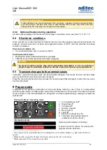
Page 28: ... 8 5 Transient changes to the nominal values In standby mode the nominal values can be transiently changed This means the new nominal values are only valid for the current step and are not saved Press the relevant nominal value box and use the numerical pad that will appear to enter the new value Confirm with Enter 9 Pause mode A program can be pause by a disruption or a manual change made by a us...

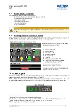
Page 29: ...eam flap off2 11 Turntable off4 12 Resume program 13 Menu item 3 14 Light off2 15 Extractor exhaust fan off2 16 Terminate all operations Back to readiness mode see item 7 Information bar System status display flashing In pause mode the reason for pausing the program will also be shown 10 Alarm signal If an alarm incident has occurred for example through digital inputs limit value alarms or sensor ...

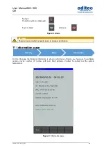
Page 30: ...Chamber sensor defect generally leads to program termination 11 Information page On the info page the following information is shown which type of device you have got the software version device number IP number with port MAC address VisuNet if enabled and the system temperature Figure 9 Information page Standby Menü Information ...

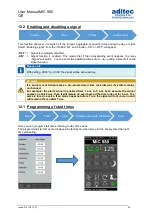
Page 31: ...time press the relevant box and use the on screen keypad to enter the new date or time Confirm with Enter on the numerical pad In order to apply this change also press the Enter button on the task bar The amended time will now appear on the info bar Figure 10 Set date time Please note The current date and Central European Time are pre set Standby Menu Profiles Standby Menu Profiles set date time ...

Page 32: ...00 the signal will be active all day Be aware If a signal event transgresses a pre programmed time lock interval its state remains unchanged For example the alarm signal in enabled from 7 a m to 5 p m Let s assume the signal comes on at 4 50 p m then it will remain on even beyond the time lock set for 5 p m The same is true vice versa If an alarm happens before 7 a m the signal will not come on an...

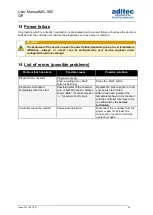
Page 33: ...blem that has arisen Possible causes Possible solutions Program does not start Program is empty Enter a waiting time Start button is flashing Press the Start button Program is terminated immediately after the start Possible defect of the chamber core or humidity sensor display shows EEE for sensor break or for sensor short circuit Replace the broken sensor or call your service technician After it ...

Page 34: ...User Manual MIC 980 Issue 21 01 2019_01 34 15 Connection diagram MIC 980 Figure 11 Connection diagram MIC 980 ...

Page 35: ...gure 1 MIC 980 6 Figure 2 Key pad 9 Figure 3 Numerical pad Eingabe 10 Figure 4 Startpage Standby 11 Figure 5 Menu 12 Figure 6 Choice of programmes 13 Figure 7 Favorites Readinessmode 13 Figure 8 Alarm 30 Figure 9 Information page 30 Figure 10 Set date time 31 Figure 11 Connection diagram MIC 980 34 ...

Page 36: ...actor exhaust fan 19 Nominal value flap time 19 Nominal value steam time 19 Notes 27 O Operating mode 29 Optional displays 25 32 P Pause mode 33 Pause mode reasons 33 Power failure 39 Profiles 14 37 program end achnowledging 31 Program terminating 31 Program starting 29 Programming mode 15 Programs 14 R Readiness mode 23 S Safety instructions 43 Sensor break 39 Sensor short circuit 39 Service 14 S...

Page 37: ...res carrying separate source voltage It is vitally important that the sensor leads have a metal shielding and that this shielding is connected to the sensor housing itself Relay outputs The relay outputs are potential free and the maximal load of 250V AC and 4A must not overshoot Water and humidity Never use the unprotected appliance near water e g near a bath tub water basin sink washing machine ...

Page 38: ...meant to do according to the user manual For servicing that exceeds his authority he should always contract a specialist Be aware Never make any technical alterations to the appliances unless they were specifically approved by aditec GmbH Unauthorized alterations will invalidate your warranty For enquiries orders and repair enquiries please contact us at the following address ...

Reviews: