background image

21

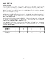
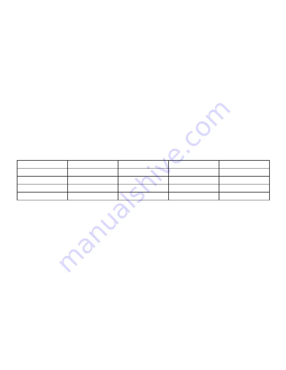
Channel Mode

Unit 1 Address

Unit 2 Address

Unit 3 Address

Unit 4 Address

1 Channels

1

2

3

4

2 Channels

1

3

5

7

3 Channels

1

4

7

10

6 Channels

1

7

13

19

D M X   S E T U P

DMX ADDRESSING
All fixtures should be given a DMX starting address when operating with a DMX controller, in order 

to ensure that the correct fixture responds to the correct control signal. This digital starting address is 

the channel number from which the fixture starts to “listen” to the digital control signal sent out from 

the DMX controller. The starting DMX address is configured by setting the correct DMX address on 

the control panel display on the fixture.
You can set the same starting address for multiple fixtures, or set different addresses for each 

individual fixture. Setting multiple fixtures to the same DMX address will cause all those fixtures to 

react in the same way. In this case, please note that changing the settings of one channel will affect 

all the fixtures simultaneously.
If you set each fixture to a different DMX address, each unit will start to “listen” to the channel number 

you have set, based on the quantity of DMX channels of each fixture. That means changing the 

settings of one channel will only affect the selected fixture.
In the case of the Encore Burst UV IP, when in 6 channel mode you should set the starting DMX 

address of the first unit to 1, the second unit to 7 (6 + 1), the third unit to 13 (7 + 6), and so on. (See 

chart below for more details.)

Summary of Contents for ENCORE BURST UV IP

Page 1: ...ENCORE BURST UV IP User Manual ...

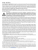
Page 2: ...lding and electrical damages injuries to any persons and direct or indirect economic loss associated with the use or reliance of any information contained within this document and or as a result of the improper unsafe insufficient and negligent assembly installation rigging and operation of this product ADJ PRODUCTS LLC World Headquarters 6122 S Eastern Ave Los Angeles CA 90040 USA Tel 800 322 633...

Page 3: ...5 7 Safety Guidelines 8 Overview 10 Torque Settings for Screws 11 Installation Omega Brackets Connections 12 13 14 System Menu 16 Dimmer Mode Chart 19 DMX Setup 20 DMX Traits 22 Daisy Chain Power Linking Cleaning and Maintenance 24 Specifications 25 Dimension Drawings 26 CONTEN T S ...

Page 4: ...shipping carton in the trash Please recycle whenever possible Parts To purchase parts online visit http parts adj com US http www adjparts eu EU ADJ SERVICE USA Monday Friday 8 00am to 4 30pm PST Voice 800 322 6337 Fax 323 582 2941 support adj com ADJ SERVICE EUROPE Monday Friday 08 30 to 17 00 CET Voice 31 45 546 85 60 Fax 31 45 546 85 96 support adj eu ADJ PRODUCTS LLC USA 6122 S Eastern Ave Los...

Page 5: ... repair labor by reason of defects in material or workmanship The sole responsibility of ADJ Products LLC under this warranty shall be limited to the repair of the product or replacement thereof including parts at the sole discretion of ADJ Products LLC All products covered by this warranty were manufactured after August 15 2012 and bear identifying marks to that effect E ADJ Products LLC reserves...

Page 6: ...he enclosed warranty card to validate your purchase All returned service items whether under warranty or not must be freight pre paid and accompanied by a return authorization R A number The R A number must be clearly written on the outside of the return package A brief description of the problem as well as the R A number must also be written down on a piece of paper included in the shipping carto...

Page 7: ...ff disconnected Inspect optics to determine if the lens is obstructed then clean optics and chassis accordingly Based on initial finding schedule maintenance accordingly keeping in mind that exterior maintenance will be required Even if the luminaires are NOT in use maintenance will still be needed given its location exterior use The use of a durable type of wax on the chassis is recommended since...

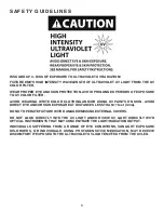
Page 8: ... TEMPERATURE RANGES FROM 4 F to 113 F 20 C TO 45 C DO NOT OPERATE THE DEVICE WHEN AMBIENT TEMPERATURE FALLS OUTSIDE OF THIS RANGE MINIMUM DISTANCE TO FLAMMABLE MATERIALS FROM THE SURFACE IS 1 6 FEET 0 5 METER DO NOT TOUCH the fixture housing during operation Turn OFF the power and allow approximately 60 minutes for the fixture to cool down before servicing DO NOT shake fixture and avoid brute force w...

Page 9: ...G UV PAINTS ON SKIN AVOID DIRECT EYE AND OR SKIN EXPOSURE AT DISTANCES LESS THAN 11 feet 3 3m DO NOT OPERATE FIXTURE WITH DAMAGED MISSING EXTERNAL COVERS DO NOT LOOK DIRECTLY INTO THE UV LIGHT AND OR VIEW UV LIGHT DIRECTLY WITH OPTICAL INSTRUMENTS THAT MAY CONCENTRATE THE LIGHT RADIATION OUTPUT INDIVIDUALS SUFFERING FROM A RANGE OF EYE CONDITIONS SUNLIGHT EXPOSURE DIS ORDERS OR INDIVIDUALS USING P...

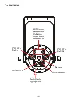
Page 10: ...10 OVERVIEW LCD Screen Mode Button Up Button Down Button Enter Button Safety Cable Rigging Point IP65 5 Pin DMX Out IP65 5 Pin DMX In IP65 Power In IP65 Power Out Air Valve ...

Page 11: ...E SETTINGS FO R SCREW S ALL SCREWS MUST BE TIGHTENED WITH A TORQUE DRIVER All screws are Allen Head screws Please see below for screw locations TORQUE DRIVERS Recommended UTICA TS 30 Shown ALTERNATIVE DRIVERS Proto J6107A Wiha 28887 Encore Burst UV IP Testing Parameters Vacuum KPA Hold time S Pressure KPA Hold time S 50KPA 60S 13KPA 60S CAUTION DO NOT OVER TORQUE SCREWS AS THIS CAN CAUSE LEAKAGE I...

Page 12: ...mbined weight of the fixture s clamps cables and accessories Ambient operating temperature range is 4 F to 113 F 20 C TO 45 C Do not operate the fixture when ambient temperature falls outside of this range Fixture s should be installed outside walking paths seating areas or areas were unauthorized personnel might reach the fixture by hand NEVER stand directly below the fixture s when rigging removing...

Page 13: ...OT FALL IF THE CLAMP FAILS SAFETY CABLE RIGGING POINT SAFETY CABLE Not Included 4 21 107mm 2 12 54mm 5 35 136mm OMEGA BRACKET CLAMP MOUNTING THE FIXTURE ON A TRUSS USING CLAMPS WITH OMEGA BRACKETS When mounting the fixture to a truss be sure to secure an appropriately rated professional grade rigging clamp to the the center hole of the Scissor Yoke or the center hole of the included Omega Bracket ...

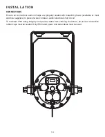
Page 14: ...dialectric grease available at most electrical suppliers to prevent water corrosion and or electrical short circuit To maintain IP65 rating integrity and prevent water from entering the fixture all unused connection rubber caps must be sealed Only IP65 rated power and date cables must be used ...

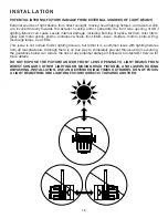
Page 15: ... shutters motors belts wiring discharge lamps and LEDs This issue is not unique to ADJ lighting fixtures but rather it is a common issue with lighting fixtures from all manufacturers Although there is no true way to completely prevent this issue from occurring the guidelines below can reduce the risk of any potential damage if followed Contact ADJ Service for more details DO NOT EXPOSE THE FIXTURE...

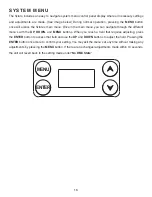
Page 16: ...rough the different menu s with the UP DOWN and MENU buttons When you reach a field that requires adjusting press the ENTER button to access that field and use the UP and DOWN buttons to adjust the field Pressing the ENTER button once more to confirm your setting You may exit the menu s at any time without making any adjustments by pressing the MENU button If there are no changes adjustments made ...

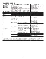
Page 17: ...Fixture Life Time Power On Time XXXXXX Hours Total Running Time Not Resettable P On Time R XXXXXX Hours Total Running Time Resettable P On Time Reset Pass Code 50 Reset Total Running Time Total LED Time LED On Time XXXXXX Hours Total LED On Running Time Not Resettable LED On Time R XXXXXX Hours LED On Running Time Resettable LED Time Reset Pass Code 50 Reset LED Running Time Fixture Temps Current ...

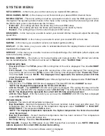
Page 18: ...nning time of the unit is displayed This running time may not be the same as the TOTAL power ON running time displayed under Power On Time This time CAN be reset NOTE The displayed time represents the current power ON time since the last reset P On Time Reset Reset the CURRENT power ON running time that is displayed under P On Time R TOTAL LED TIME LED On Time The TOTAL LED ON time is displayed Th...

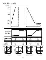
Page 19: ...ime ms Down Time ms Rise Time ms Down Time ms Standard default 0 0 0 0 Stage 780 1100 1540 1660 TV 1180 1520 1860 1940 Architectural 1380 1730 2040 2120 Theatre 1580 1940 2230 2280 Stage 2 0 1100 0 1660 0 255 0 255 100 Output DMX LINEAR DMX 0 100 Output DMX SQUARE DMX 0 100 Output DMX INVERSE SQUARE DMX 0 100 Output DMX S CURVE DMX 0 ...

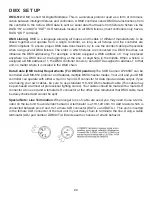
Page 20: ...a DMX address of 1 the DMX controller knows to send DATA assigned to address 1 to that unit no matter where it is located in the DMX chain Data Cable DMX Cable Requirements For DMX Operation The COB Cannon LP200ST can be controlled via DMX 512 protocol and features multiple DMX channel modes Your unit and your DMX controller can operate with either a 3 pin or 5 pin XLR connector for data input and...

Page 21: ...the fixture You can set the same starting address for multiple fixtures or set different addresses for each individual fixture Setting multiple fixtures to the same DMX address will cause all those fixtures to react in the same way In this case please note that changing the settings of one channel will affect all the fixtures simultaneously If you set each fixture to a different DMX address each u...

Page 22: ...D On 192 223 Random Strobing Slow Fast 224 255 LED On DIMMER MODES 000 020 Standard Stage 021 040 Stage 041 060 TV 061 080 Architectural 081 100 Theatre 101 120 Stage 2 DIMMER DELAY TIME 121 0 1 Sec 122 0 2 Sec 123 0 3 Sec 124 0 4 Sec 125 0 5 Sec 126 0 6 Sec 127 0 7 Sec 128 0 8 Sec 129 0 9 Sec 130 1 0 Sec 131 1 5 Sec 132 2 0 Sec 133 3 0 Sec 134 4 0 Sec 135 5 0 Sec 136 6 0 Sec 137 7 0 Sec 138 8 0 S...

Page 23: ...00Hz 046 060 1100Hz 061 075 1200Hz 076 090 1300Hz 091 105 1400Hz 106 120 1500Hz 121 135 2500Hz 136 150 4000Hz 151 165 5000Hz 166 180 6000Hz 181 195 10000Hz 196 210 15000Hz 211 225 20000Hz 226 255 25000Hz 6 GAMMA 000 020 Default to Unit Setting 021 040 1 0 041 060 2 0 061 080 2 2 081 100 2 4 101 120 2 6 121 130 2 8 131 255 No Function ...

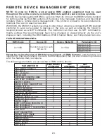
Page 24: ...Channel Mode and Temperature Sensors FIXTURE RDM INFORMATION Please be aware that not all RDM devices support all RDM features and therefore it is important to check beforehand to ensure that the equipment that you are considering includes all of the features that you require The following parameters are accessible in RDM on this device RDM Code Device ID Device Model ID Personality ID 0x1900 Rand...

Page 25: ...r inspections are recommended to ensure proper function and extended life There are no user serviceable parts inside this fixture Please refer all other service issues to an authorized ADJ service technician Should you need any spare parts please order genuine parts from your local ADJ dealer Please refer to the following points during routine inspections A detailed electrical check by an approved ...

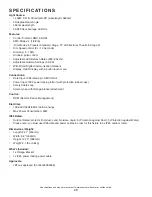
Page 26: ...In Out Power Input IP65 power locking In Out with protective rubber caps Safety Cable Loop Scissor yoke with Omega bracket attachment Control RDM Remote Device Management Electrical 100 240V 50Hz 60Hz Auto Sensing Max Power Consumption 63W IP65 Rated Outdoor Rated protects from dust sand moisture liquid 6 Protection against Dust 5 Protection against Water Please note you must use IP65 data and pow...

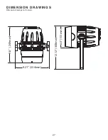
Page 27: ...27 DIMENSIO N DRAW I N GS Dimension drawings not to scale 9 8 249mm 9 21 234mm 12 12 308mm 6 0 153mm ...

Page 28: ......
Reviews: