ADJ Products, LLC - www.adj.com - Fog Fury Jett Instruction Manual Page 4
ADJ Products, LLC - www.adj.com - Fog Fury Jett Instruction Manual Page 5
Power Supply:
Before plugging your unit in, be sure the source volt-
age in your area matches the required voltage for your ADJ Fog Fury
Jett. The ADJ Fog Fury Jett is available in a 120v and 230v version.
Because line voltage may vary from venue to venue, you should be
sure your unit voltage matches the wall outlet voltage before attempt-
ing to operate you fixture.
DMX-512:
DMX is short for Digital Multiplex. This is a universal pro-
tocol used as a form of communication between intelligent fixtures
and controllers. A DMX controller sends DMX data instructions from
the controller to the fixture. DMX data is sent as serial data that trav-
els from fixture to fixture via the DATA “IN” and DATA “OUT” XLR ter-
minals located on all DMX fixtures (most controllers only have a DATA
“OUT” terminal).
DMX Linking:
DMX is a language allowing all makes and models of
different manufactures to be linked together and operate from a single
controller, as long as all fixtures and the controller are DMX compli-
ant. To ensure proper DMX data transmission, when using several
DMX fixtures try to use the shortest cable path possible. The order
in which fixtures are connected in a DMX line does not influence the
DMX addressing. For example; a fixture assigned a DMX address of 1
may be placed anywhere in a DMX line, at the beginning, at the end,
or anywhere in the middle. When a fixture is assigned a DMX address
of 1, the DMX controller knows to send DATA assigned to address 1
to that unit, no matter where it is located in the DMX chain.
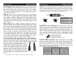
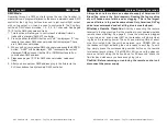
Data Cable (DMX Cable) Requirements (For DMX Operation):
The Fog Fury Jett can be controlled via DMX-512 protocol. The Fog Fury
Jett has 5 DMX channel modes. The DMX address is set on the back
panel. Your unit and your DMX controller require a standard 3-pin XLR
connector for data input and data output (Figure 1).
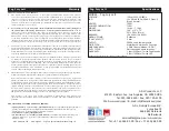
We recommend Accu-Cable DMX cables. If you are
making your own cables, be sure to use standard
110-120 Ohm shielded cable (This cable may be pur-
chased at almost all pro lighting stores). Your cables
should be made with a male and female XLR con-
nector on either end of the cable. Also remember
that DMX cable must be daisy chained and cannot
be split.
Figure 1
Notice:
Be sure to follow figures two and three when making your own
cables. Do not use the ground lug on the XLR connector. Do not con-
nect the cable’s shield conductor to the ground lug or allow the shield
conductor to come in contact with the XLR’s outer casing. Grounding
the shield could cause a short circuit and erratic behavior.
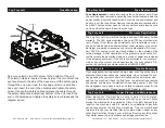
DMX512 IN
3-PIN XLR
SOUND
REMOTE
CONTROL
INPUT
POWER
INPUT OUTPUT
SOUND
REMOTE
CONTROL
INPUT
POWER
INPUT OUTPUT
SOUND
REMOTE
CONTROL
INPUT
POWER
INPUT OUTPUT
DMX512
DMX+,DMX-,COMMON
1
2
3
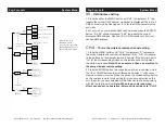
Termination reduces signal errors and
avoids signal transmission problems
and interference. It is always advisable
to connect a DMX terminal, (Resistance
120 Ohm 1/4 W) between PIN 2 (DMX-)
and PIN 3 (DMX +) of the last fixture.
1
2
3
1
2
3
DMX +
DMX -
COMMON
DMX512 OUT
3-PIN XLR
Figure 2
Figure 3
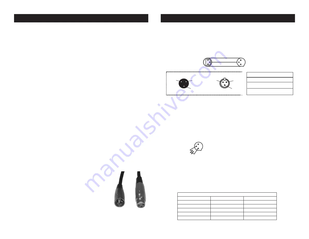
1 Ground
1 Ground
XLR Male Socket
XLR Pin Configuration
3 Hot
2 Cold
2 Cold
3 Hot
XLR Female Socket
Pin 3 = Data True (positive)
Pin 2 = Data Compliment (negative)
Pin 1 = Ground
Special Note: Line Termination.
When longer runs of cable are
used, you may need to use a terminator on the last unit to avoid erratic
behavior. A terminator is a 110-120 ohm 1/4 watt resistor which is con-
nected between pins 2 and 3 of a male XLR connector (DATA + and
DATA -). This unit is inserted in the female XLR connector of the last
unit in your daisy chain to terminate the line. Using a cable terminator
(ADJ part number Z-DMX/T) will decrease the possibilities of erratic
behavior.
DMX512 IN
3-PIN XLR
SOUND
REMOTE
CONTROL
INPUT
POWER
INPUT OUTPUT
SOUND
REMOTE
CONTROL
INPUT
POWER
INPUT OUTPUT
SOUND
REMOTE
CONTROL
INPUT
POWER
INPUT OUTPUT
DMX512
DMX+,DMX-,COMMON
1
2
3
Termination reduces signal errors and
avoids signal transmission problems
and interference. It is always advisable
to connect a DMX terminal, (Resistance
120 Ohm 1/4 W) between PIN 2 (DMX-)
and PIN 3 (DMX +) of the last fixture.
1
2
3
1
2
3
DMX +
DMX -
COMMON
DMX512 OUT
3-PIN XLR
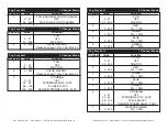
Figure 4
5-Pin XLR DMX Connectors.
Some manufactures use 5-pin DMX-
512 data cables for DATA transmission in place of 3-pin. 5-pin DMX
fixtures may be implemented in a 3-pin DMX line. When inserting stan-
dard 5-pin data cables in to a 3-pin line a cable adaptor must be used,
these adaptors are readily available at most electric stores. The chart
below details a proper cable conversion.
Conductor
5-Pin XLR Male (In)
3-Pin XLR Female (Out)
Pin 1
Do Not Use
Do Not Use
Pin 3
Pin 2
Pin 1
Pin 3
Pin 2
Not Used
Not Used
Data True (+ signal)
Data Compliment (- signal)
Ground/Shield
3-Pin XLR to 5-Pin XLR Conversion
Fog Fury Jett
DMX Information
Fog Fury Jett
DMX Information


