background image

©2019 ADJ Products, LLC all rights reserved. Information, specifications, diagrams, images, and 

instructions herein are subject to change without notice. ADJ Products, LLC logo and identifying 

product names and numbers herein are trademarks of ADJ Products, LLC. Copyright protection 

claimed includes all forms and matters of copyrightable materials and information now allowed by 

statutory or judicial law or hereinafter granted. Product names used in this document may be 

trademarks or registered trademarks of their respective companies and are hereby acknowledged. 

All non-ADJ Products, LLC brands and product names are trademarks or registered trademarks of 

their respective companies.
ADJ Products, LLC and all affiliated companies hereby disclaim any and all liabilities for property, 

equipment, building, and electrical damages, injuries to any persons, and direct or indirect economic 

loss associated with the use or reliance of any information contained within this document, and/or as 

a result of the improper, unsafe, unsufficient and negligent assembly, installation, rigging, and operation 

of this product.

Europe Energy Saving Notice

Energy Saving Matters (EuP 2009/125/EC)

Saving electric energy is a key to help protecting the enviroment. Please turn off all electrical products when 

they are not in use. To avoid power consumption in idle mode, disconnect all electrical equipment from power 

when not in use. Thank you!

FCC STATEMENT

This device complies with Part 15 of the FCC Rules. Operation is subject to the following two conditions: 

(1) this device may not cause harmful interference, and (2) this device must accept any interference 

received, including interference that may cause undesired operation.
FCC RADIO FREQUENCY INTERFERENCE WARNINGS & INSTRUCTIONS

This product has been tested and found to comply with the limits as per Part 15 of the FCC Rules. These 

limits are designed to provide reasonable protection against harmful interference in a residential installation. 

This device uses and can radiate radio frequency energy and, if not installed and used in accordance with 

the included instructions, may cause harmful interference to radio communications. However, there is no 

guarantee that interference will not occur in a particular installation. If this device does cause harmful 

interference to radio or television reception, which can be determined by turning the device off and on, the 

user is encouraged to try to correct the interference by one or more of the following methods:


·         Reorient or relocate the device.

·         Increase the separation between the device and the receiver.

·         Connect the device to an electrical outlet on a circuit different from which the radio receiver is 

          connected.

·         Consult the dealer or an experienced radio/TV technician for help.

DOCUMENT VERSION

Due to additional product features and/or enhancements, an updated version of this document 

may be available online. 

Please check 

www.adj.com 

 for the latest revision/update of this manual before beginning 

installation and/or programming.

Date

Document

Version

Software

Version

DMX

Channel

Mode

Notes

>

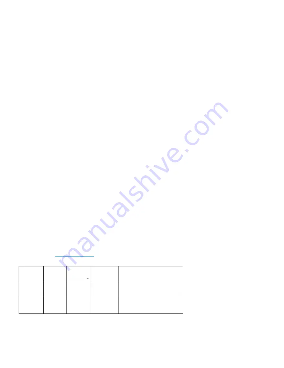
01/19/18

1

1.00

4/5/6/9/10 Initial Release

03/20/19

1.2

1.01

No Change IR Remote Functions Updated

Summary of Contents for MOD QW100

Page 1: ...User Instructions MOD QW100 ...

Page 2: ...ation is subject to the following two conditions 1 this device may not cause harmful interference and 2 this device must accept any interference received including interference that may cause undesired operation FCC RADIO FREQUENCY INTERFERENCE WARNINGS INSTRUCTIONS This product has been tested and found to comply with the limits as per Part 15 of the FCC Rules These limits are designed to provide...

Page 3: ...Precautions Control Panel Layout DMX Set Up DMX Addressing DMX Channel Modes System Menu Operating Instructions Master Slave Configuration UC IR Airstream IR Control Dimmer Curve Chart Dimensional Drawings Housing Change Frost Filter Power Linking Trouble Shooting Cleaning Warranty Technical Specifications 3 4 5 7 8 25 26 27 28 29 31 30 9 24 20 10 21 ...

Page 4: ...the basic operations of this unit These instructions contain important safety information regarding the use and maintenance of this unit Please keep this manual with the unit for future reference Customer Support Contact ADJ Service for any product related service and support needs Also visit forums adj com with questions comments or suggestions Parts To purchase parts online visit http parts amer...

Page 5: ... the problem as well as the R A number must also be written down on a piece of paper included in the shipping carton If the unit is under warranty you must provide a copy of your proof of purchase invoice You may obtain a R A number by con tacting our customer support team on our customer support number All packages returned to the service department not displaying a R A number on the outside of t...

Page 6: ... this unit if it becomes damaged This unit is intended for indoor use only use of this product outdoors voids all warranties During long periods of non use disconnect the unit s main power Always mount this unit in safe and stable matter Power supply cords should be routed so that they are not likely to be walked on or pinched by items placed upon or against them paying particular attention to the...

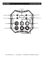
Page 7: ...com MOD QW100 User Manual Page 6 MOD QW100 Control Panel Layout SET UP MODE UP DOWN DMX IN DMX OUT DMX OUT POWER OUT DMX IN POWER IN MODE BUTTON SET UP BUTTON UP BUTTON DOWN BUTTON LCD DISPLAY POWER IN POWER OUT DMX IN DMX OUT ...

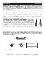
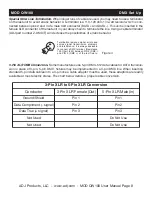
Page 8: ... be controlled via DMX 512 protocol The MOD QW100 has 5 DMX channel modes The DMX address is set on the rear panel of the MOD QW100 Your unit and your DMX controller require a standard 3 pin XLR connector for data input and data output Figure 1 We recommend Accu Cable DMX cables If you are making your own cables be sure to use standard 110 120 Ohm shielded cable This cable may be purchased at almo...

Page 9: ...blems and interference It is always advisable to connect a DMX terminal Resistance 120 Ohm 1 4 W between PIN 2 DMX and PIN 3 DMX of the last fixture 1 2 3 Figure 4 5 Pin XLR DMX Connectors Some manufactures use 5 pin DMX 512 data cables for DATA transmis sion in place of 3 pin 5 pin DMX fixtures may be implemented in a 3 pin DMX line When inserting standard 5 pin data cables in to a 3 pin line a c...

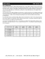
Page 10: ...all fixtures to the same DMX address will cause all fixtures to react in the same way in other words changing the settings of one channel will affect all the fixtures simultaneously If you set each fixture to a different DMX address each unit will start to listen to the channel number you have set based on the quantity of DMX channels of each fixture That means changing the settings of one channel...

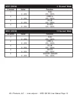
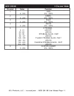
Page 11: ...0 4 Channel Mode Channel Value Function 1 RED 0 255 0 100 2 GREEN 0 255 0 100 3 BLUE 0 255 0 100 4 WHITE 0 255 0 100 MOD QW100 5 Channel Mode Channel Value Function 1 RED 0 255 0 100 2 GREEN 0 255 0 100 3 BLUE 0 255 0 100 4 WHITE 0 255 0 100 5 MASTER DIMMER 0 255 0 100 ...

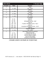
Page 12: ... Value Function 1 RED 0 255 0 100 2 GREEN 0 255 0 100 3 BLUE 0 255 0 100 4 WHITE 0 255 0 100 5 STROBING 0 31 LED OFF 32 63 LED ON 64 95 STROBING SLOW FAST 96 127 LED ON 128 159 PULSE STROBING SLOW FAST 160 191 LED ON 192 223 RANDOM STROBING SLOW FAST 224 255 LED ON 6 MASTER DIMMER 0 255 0 100 ...

Page 13: ... STROBING 0 31 LED OFF 32 63 LED ON 64 95 STROBING SLOW FAST 96 127 LED ON 128 159 PULSE STROBING SLOW FAST 160 191 LED ON 192 223 RANDOM STROBING SLOW FAST 224 255 LED ON 6 MASTER DIMMER 0 255 0 100 7 PROGRAM SELECTION MODE 0 51 DIMMING MODE 52 102 COLOR MACRO MODE 103 153 COLOR CHANGE MODE 154 204 COLOR FADE MODE 205 255 SOUND ACTIVE MODE 9 CHANNEL MODE IS CONTINUED ON THE NEXT PAGE ...

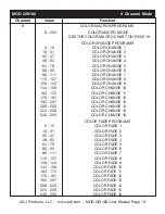
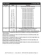
Page 14: ...112 127 COLOR CHANGE 8 128 143 COLOR CHANGE 9 144 159 COLOR CHANGE 10 160 175 COLOR CHANGE 11 176 191 COLOR CHANGE 12 192 207 COLOR CHANGE 13 208 223 COLOR CHANGE 14 224 239 COLOR CHANGE 15 240 255 COLOR CHANGE 16 COLOR FADE PROGRAMS 0 15 COLOR FADE 1 16 31 COLOR FADE 2 32 47 COLOR FADE 3 48 63 COLOR FADE 4 64 79 COLOR FADE 5 80 95 COLOR FADE 6 96 111 COLOR FADE 7 112 127 COLOR FADE 8 128 143 COLO...

Page 15: ... MODE 15 240 255 SOUND ACTIVE MODE 16 9 PROGRAM SPEED SOUND SENSITIVITY 0 255 PROGRAM SPEED SLOW FAST 0 255 SOUND SENSITIVITY LEAST MOST SENSITIVE When Channel 7 is between the values of 0 51 Channels 1 4 are used and Channel 5 will control strobing When Channel 7 is between the values of 52 102 Channel 8 is in Color Macros Mode and Channel 5 will control strobing When Channel 7 is between the val...

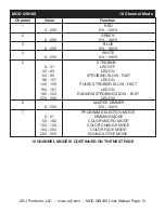
Page 16: ... STROBING 0 31 LED OFF 32 63 LED ON 64 95 STROBING SLOW FAST 96 127 LED ON 128 159 PULSE STROBING SLOW FAST 160 191 LED ON 192 223 RANDOM STROBING SLOW FAST 224 255 LED ON 6 MASTER DIMMER 0 255 0 100 7 PROGRAM SELECTION MODE 0 51 DIMMING MODE 52 102 COLOR MACRO MODE 103 153 COLOR CHANGE MODE 154 204 COLOR FADE MODE 205 255 SOUND ACTIVE MODE 10 CHANNEL MODE IS CONTINUED ON THE NEXT PAGE ...

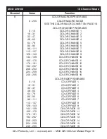
Page 17: ...112 127 COLOR CHANGE 8 128 143 COLOR CHANGE 9 144 159 COLOR CHANGE 10 160 175 COLOR CHANGE 11 176 191 COLOR CHANGE 12 192 207 COLOR CHANGE 13 208 223 COLOR CHANGE 14 224 239 COLOR CHANGE 15 240 255 COLOR CHANGE 16 COLOR FADE PROGRAMS 0 15 COLOR FADE 1 16 31 COLOR FADE 2 32 47 COLOR FADE 3 48 63 COLOR FADE 4 64 79 COLOR FADE 5 80 95 COLOR FADE 6 96 111 COLOR FADE 7 112 127 COLOR FADE 8 128 143 COLO...

Page 18: ... SENSITIVITY 0 255 PROGRAM SPEED SLOW FAST 0 255 SOUND SENSITIVITY LEAST MOST SENSITIVE 10 DIMMER CURVES 0 20 STANDARD 21 40 STAGE 41 60 TV 61 80 ARCHITECTURAL 81 100 THEATRE 101 255 DEFAULT TO UNIT SETTING When Channel 7 is between the values of 0 51 Channels 1 4 are used and Channel 5 will control strobing When Channel 7 is between the values of 52 102 Channel 8 is in Color Macros Mode and Chann...

Page 19: ... 45 48 255 71 77 71 Color45 Color13 49 52 255 83 134 83 Color46 Color14 53 56 255 93 182 93 Color47 Color15 57 60 255 96 236 96 Color48 Color16 61 64 238 93 255 93 Color49 Color17 65 68 196 87 255 87 Color50 Color18 69 72 150 90 255 90 Color51 Color19 73 76 100 77 255 77 Color52 Color20 77 80 77 100 255 77 Color53 Color21 81 84 67 148 255 67 Color54 Color22 85 88 77 195 255 77 Color55 Color23 89 9...

Page 20: ...lor43 169 172 119 130 199 0 74 Color44 173 176 147 164 212 0 71 Color45 177 180 88 2 163 0 83 Color46 181 184 0 38 86 0 93 Color47 185 188 0 142 208 0 96 Color48 189 192 52 148 209 0 93 Color49 193 196 1 134 201 0 87 Color50 197 200 0 145 212 0 90 Color51 201 204 0 121 192 0 77 Color52 205 208 0 129 184 0 77 Color53 209 212 0 83 115 0 67 Color54 213 216 0 97 166 0 77 Color55 217 220 1 100 167 0 77...

Page 21: ...reen color MANUAL BLUE 000 255 Adjust the intensity of the blue color MANUAL WHIT 000 255 Adjust the intensity of the white color MANUAL STROB 00 15 Adjust the flash speed 00 is flash off 01 is slowest 15 is fastest JUMP RUN SNAP 01 16 Select the 16 color change modes JUMP RUN SPEED 01 16 Adjust the speed of the color change mode FADE RUN SNAP 01 16 Select the 16 color dreaming modes FADE RUN SPEE...

Page 22: ... will run a combination of color change and color fade The speed is adjustable Static Color Mode There are 63 colors to choose from DMX control mode This function will allow you to control each individual fixtures traits with a standard DMX 512 controller DMX Mode Operating through a DMX controller gives the user the freedom to create their own programs tai lored to their own individual needs The ...

Page 23: ...3 Press the SET UP button and SPEED XX will be displayed Use the UP and DOWN buttons to adjust the speed of the color change The speed can be adjusted between 01 slowest to 16 fastest Color Fade Mode 1 Plug the fixture in and press the MODE button until FADE RUN SNAP XX is displayed XX represents a number between 01 16 2 Use the UP and DOWN buttons to find your desired color fade mode 3 Press the ...

Page 24: ...AY X is displayed X represents the displayed dimmer curve 0 4 0 Standard 1 Stage 2 TV 3 Architectural 4 Theatre 3 Press the UP or DOWN buttons to scroll through and select your desired dimming curve DMX State This mode can be used as a precaution mode that in case the DMX signal is lost the operat ing mode chosen in the setup is the running mode the fixture will go into when the DMX signal is lost...

Page 25: ...g units running mode Any unit can act as a Master or as a Slave however only one unit can be programmed to act as the Master Master Slave Connections and Settings 1 Daisy chain the units via the XLR connectors on the bottom of the unit Use standard XLR data cables to link the units together Remember that the Male XLR connector is the input and the Female XLR connector is the ouput The first unit i...

Page 26: ... DIMMER Use these buttons to adjust the output intensity when either color macro mode color change mode color fade mode is active STROBE Press this button to activate strobing Use buttons 1 4 to adjust the strobe speed 1 being the slowest 4 being the fastest Press this button again to stop strobing COLOR Press this button to activate color macro mode Use the numeral buttons 1 9 to select your desi...

Page 27: ...Numeral Buttons 1 9 Use buttons 1 9 to select your desired color in static color mode or your desired program in color fade mode and color change mode Use buttons 1 4 to select a desired strobe rate when strobing is active SOUND ON OFF Use the buttons to activate and deactivate sound active mode When activated sound sensitivity is at the highest When SOUND OFF is pressed sensitvity is at its lowes...

Page 28: ...ADJ Products LLC www adj com MOD QW100 User Manual Page 27 MOD QW100 Dimensional Drawing 9 9 251 5mm 5 48 139 33mm 5 5 140mm 7 75 197mm 6 77 172mm 8 75 222mm ...

Page 29: ...W100 Frost Filter The MOD units housing is interchangeable You can purchase the white housing kit through ADJ Changing the housing is very simple process Follow the instructions below to change the housing For more help contact ADJ Customer Support The MOD QW100 comes with 3 interchangeable frost filters To install the frost filter unscrew the four thumb screws holding lens in place Remove the len...

Page 30: ...nternal and external optical lenses must be carried out periodically to optimize light output 1 Use normal glass cleaner and a soft cloth to wipe down the outside casing 2 Clean the external optics with glass cleaner and a soft cloth every 20 days 3 Always be sure to dry all parts completely before plugging the unit back in Cleaning frequency depends on the environment in which the fixture operate...

Page 31: ...of defects in material or workmanship The sole responsibility of ADJ Products LLC under this warranty shall be limited to the repair of the product or replacement thereof including parts at the sole discretion of ADJ Products LLC All products covered by this warranty were manufactured after August 15 2012 and bear indentifying marks to that effect E ADJ Products LLC reserves the right to make chan...

Page 32: ...20V 9 Fixtures Max 240V Weight 6 lbs 2 7 Kgs Dimensions 10 37 L x 7 71 W x 8 75 H 263 4 x 196 x 222mm Colors RGBW Color Mixing DMX Channels 5 DMX Modes 4 5 6 9 10 Warranty 2 Year 730 days Please Note Specifications and improvements in the design of this unit and this manual are subject to change without any prior written notice ADJ Products LLC www adj com MOD QW100 User Manual Page 31 ...

Reviews: