background image

A.D.J. Supply Europe B.V. – www.americandj.eu – Mystic LED  Instruction Manual Page 5 


SET UP (continued) 


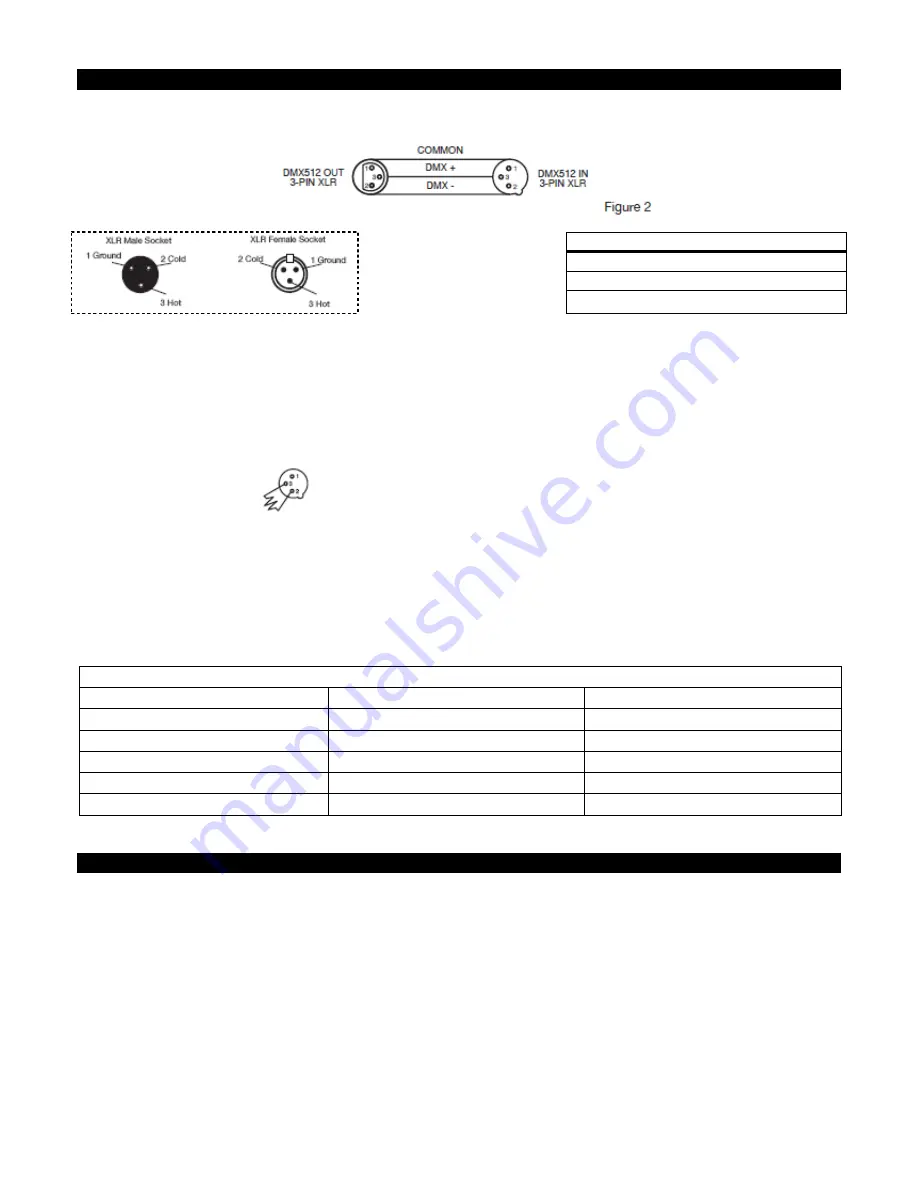
XLR Pin Configuration 


Pin1 = Ground 


Pin2 = Data Compliment (negative) 


Pin3 = Data True (positive) 

Figure 3 

Special Note: Line Termination. 

When longer runs of cable are used, you may need to use a terminator on 

the  last  unit  to  avoid  erratic  behavior.  A  terminator  is  a  90-120  ohm  1/4  watt  resistor  which  is  connected 
between pins 2 and 3 of a male XLR connector (DATA + and DATA -). This unit is inserted in the female XLR 
connector of the last unit in your daisy chain to terminate the line. Using a cable terminator (ADJ part number 
Z-DMX/T) will decrease the possibilities of erratic behavior. 


Termination  reduces  signal  errors  and  avoids 
signal transmission problems and interference.  
It  is  always  advisable  to  connect  a  DMX 
terminal,  (Resistance120  Ohm  1/4  W)  between 
PIN  2  (DMX-)  and  PIN  3  (DMX  +)  of  the  last 
fixture. 


Figure 4 


5-Pin XLR DMX Connectors. 

Some manufactures use 5-pin DMX-512 data cables for DATA transmission in 

place  of  3-pin.  5-pin  DMX  fixtures  may  be  implemented  in  a  3-pin  DMX  line. When  inserting  standard  5-pin 
data  cables  in  to  a  3-pin  line  a  cable  adaptor  must  be  used,  these  adaptors  are  readily  available  at  most 
electric stores. The chart below details a proper cable conversion 

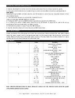
3-Pin XLR to 5-Pin XLR Conversion


Conductor 

3-pin XLR Female (Out) 

5-pin XLR Male (In) 

Ground/Shield 

Pin 1 

Pin 1 

Data compliment (- signal) 

Pin 2 

Pin 2 

Data True (+ signal) 

Pin 3 

Pin 3 

Not used 


Do Not Use 

Not used 


Do Not Use 


SYSTEM MENU 

MAIN MENU -


A.001 

-

 DMX Address Setting 


1. Press the ESCAPE button to get to the main menu. Press the UP button until “A001” is displayed and press 
ENTER.  
2. Tap the UP or DOWN buttons until the address that you want is displayed and press ENTER.  

TEST 

This  function  will  activate  the  preset  program.  To  run  the  preset  program  Sound  Active 

mode must be OFF.


1. Press the ESCAPE (ESC) button to get to the main menu. Press the UP button until “TEST” is displayed 
and press EN-  

Summary of Contents for Mystic Led

Page 1: ...User Instructions A D J Supply Europe B V Junostraat 2 6468 EW Kerkrade The Netherlands www americandj eu 3 08...

Page 2: ...3 GENERAL INSTRUCTIONS 3 FEATURES 3 SAFETY PRECAUTIONS 3 SET UP 4 SYSTEM MENU 5 OPERATING INSTRUCTIONS 6 FUSE REPLACEMENT 8 DMX TRAITS 8 CLEANING 9 TROUBLE SHOOTING 9 SPECIFICATIONS 10 ROHS A GREAT CO...

Page 3: ...EASE recycle the shipping carton whenever possible GENERAL INSTRUCTIONS To optimize the performance of this product please read these operating instructions carefully to familiarize yourself with the...

Page 4: ...ia the DATA IN and DATA OUT XLR terminals located on all DMX fixtures most controllers only have a DATA OUT terminal DMX Linking DMX is a language allowing all makes and models of different manufactur...

Page 5: ...ast fixture Figure 4 5 Pin XLR DMX Connectors Some manufactures use 5 pin DMX 512 data cables for DATA transmission in place of 3 pin 5 pin DMX fixtures may be implemented in a 3 pin DMX line When ins...

Page 6: ...ntil TEST is displayed and press ENTER 2 MODE 1 will now be displayed press ENTER 3 The fixture will now run the preset program 4 The optional UC3 Controller not included may be used to control differ...

Page 7: ...A D J Supply Europe B V www americandj eu Mystic LED Instruction Manual Page 7 You do not have to assign the units Master Slave They will automatically fall into Master Slave mode...

Page 8: ...ous DMX fixture traits FUSE REPLACEMENT Locate and remove the unit s power cord Once the cord has been removed located the fuse holder located inside the power socket Insert a flat head screw driver i...

Page 9: ...unit back in Cleaning frequency depends on the environment in which the fixture operates i e smoke fog residue dust dew TROUBLE SHOOTING Listed below are a few common problems the user may encounter w...

Page 10: ...ht Dimensions Colors Working Position Mystic LED 120V 60Hz 230V 50Hz 224 5mm LEDs 88 Red 48 Green 88 Blue 3 Amp 10bs 4 5Kgs 18 5 L x 14 75 W x 14 75 H RGB Any safe working position Please Note Specifi...

Page 11: ...lectromagnetic fields in short each kind of electronics we have around us in our households or at work As manufacturers of products of the brands of AMERICAN AUDIO AMERICAN DJ ELATION Professional and...

Page 12: ...to develop a common system of waste management Thereby we can ensure professional and environmentally friendly scraping and recycling program As manufactures we are part of the German system of EAR an...

Page 13: ...A D J Supply Europe B V www americandj eu Mystic LED Instruction Manual Page 13 A D J Supply Europe B V Junostraat 2 6468 EW Kerkrade The Netherlands www americandj eu...

Reviews: