4
Introduction
*Specifications are subject to change without notice.
DC Output Table
The combined output power of +5V and +3.3V shall not exceed 35A.
Storage environment
Ambient temperature
PXIS-2508
-20°C to 70°C
PXIS-2558T
0°C to 70°C
Relative humidity
10% to 90%, non-condensing
Shock and vibration
Functional shock
30 G half-sine, 11 ms pulse duration
Random vibration
Operating
5 Hz to 500 Hz, 0.5 Grms, 3 axes
Non-operating
5 Hz to 500 Hz, 2.46 Grms, 3 axes
Certifications
Safety
IEC 61010-1/EN 61010-1
Electromagnetic compatibility
Emissions
EN 55011 Class A
Immunity
EN 61326-1
CE compliance
The PXIS-2508 and PXIS-2558T meet the
essential requirements of applicable European
Directives
1
See DC Output Table below.
2
Measured at operator position, tested in accordance with ISO 7779:1999/
Amd.1:2003(E)
3
Tested in accordance with ISO 7779:1999/Amd.1:2003(E)
VDC
Minimum
Maximum
Load
Regulation
Max. Ripple
& Noise
+5 V
3.0 A
35 A
±5%
50 mV
+12 V
2.0 A
18 A
±5%
120 mV
+3.3 V
1.0 A
20 A
±5%
50 mV
-12 V
0.1 A
2 A
±10%
150 mV
Summary of Contents for 96864-1
Page 11: ......
Page 17: ...6 Introduction ...
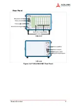
Page 20: ...Chassis Overview 9 Rear Panel Figure 2 2 PXIS 2508 2558T Rear Panel Foot stand ...
Page 21: ...10 Chassis Overview Left Panel Figure 2 3 PXIS 2508 2558T Left Panel ...
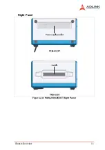
Page 22: ...Chassis Overview 11 Right Panel Figure 2 4 PXIS 2508 2558T Right Panel ...
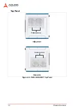
Page 23: ...12 Chassis Overview Top Panel Figure 2 5 PXIS 2508 2558T Top Panel ...
Page 24: ...Chassis Overview 13 Base Panel Figure 2 6 PXIS 2508 2558T Base Panel ...
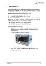
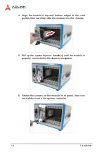
Page 31: ...20 Installation 5 Fasten the screw on the module front panel then con nect all devices ...
Page 41: ...30 Installation ...
Page 53: ...42 Remote Management ...


