


12
System Description
Leading
EDGE COMPUTING
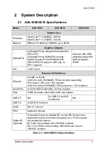
2.5
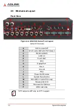
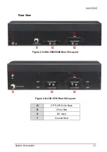
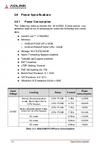
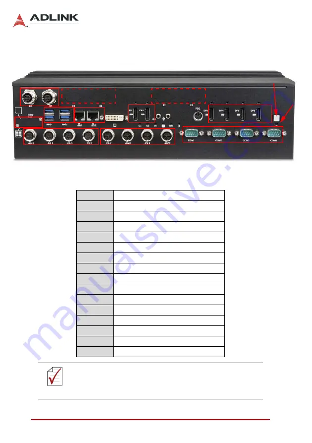
Mechanical Layout
Front View
Figure 2-4: AVA-5500 Series Front Layout
(
AVA-5510 shown)
A
M12 A-code GbE
B
M12 X-code GbE with PoE Class 2
C
RS232/422/485
D
USB 3.0
E
RJ-45 GbE
F
DVI-I
G
DisplayPort*
H
Mic-in
I
Line-out
J
PS/2
K
Power On/Off button
L
System Reset button
M
M12 USB 2.0 (AVA-5510 only)
N
Reserved for DIO
O
Reserved for CAN bus
P
USIM card slots
NOTE:
NOTE:
*DP3 output is eDP only, no DP++ support.
B
C
K
L
D
E
F
G
G
H I
M
N
O
J
P
A
Summary of Contents for AVA-5500 Series
Page 8: ...viii Table of Contents Leading EDGE COMPUTING This page intentionally left blank ...
Page 10: ...x List of Figures Leading EDGE COMPUTING This page intentionally left blank ...
Page 12: ...xii List of Tables Leading EDGE COMPUTING This page intentionally left blank ...
Page 76: ...64 BIOS Setup Leading EDGE COMPUTING This page intentionally left blank ...


