32
Interfaces
Leading
EDGE COMPUTING
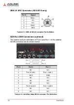
USB 2.0 M12 Connector (AVA-5510 only)
Table 4-11: USB 2.0 M12 Connector Pin Definition
CAN Bus DB9 Connectors (optional)
The location and pin definitions of Port 0 and Port 1 of the optional
CAN Bus module are as shown below.
Table 4-12: CAN Bus Male DB9 Connector Pin Definition
Pin #
Signal
1
Data -
2
+5V
3
NC
4
Data +
5
GND
Pin #
Port 0
Port 1
1
NC
NC
2
Port 0 CAN L
Port 1 CAN L
3
GND
GND
4
NC
NC
5
NC
NC
6
NC
NC
7
Port 0 CAN H
Port 1 CAN H
8
NC
NC
9
NC
NC
Port 0 Port 1
Pin 5
Pin 9
Pin 1
Pin 6
Summary of Contents for AVA-5500 Series
Page 8: ...viii Table of Contents Leading EDGE COMPUTING This page intentionally left blank ...
Page 10: ...x List of Figures Leading EDGE COMPUTING This page intentionally left blank ...
Page 12: ...xii List of Tables Leading EDGE COMPUTING This page intentionally left blank ...
Page 76: ...64 BIOS Setup Leading EDGE COMPUTING This page intentionally left blank ...

